Negative loop feedback in general not only reduces distortion it also increases bandwidth among other things. In other words it dominates over several open loop shortcomings. One of those is impact of the Miller effect. Unfortunately allocating too much gain elsewhere than at the input stage also goes against good noise management principles which are central in phono design. On the other hand some use of local negative feedback can be a sensible compromise.
You need enough first stage gain so that the noise is dominated by that first stage. You certainly don't what the noise to be dominated by the second stage.
sawyers is right, if you have at least 20db gain in the first stage, the first stage noise will dominate.
Thank you Marcel - that makes a lot of sense.
So calculating the open loop gain (as you'd normally do to check for gain and phase margins) is actually misleading, because it overestimates the input capacitance. You only get the first stage Miller capacitance modification/reduction once you close the loop, provided the second stage gain is high enough.
Am I reading that right?
Yes.
Negative loop feedback in general not only reduces distortion it also increases bandwidth among other things. In other words it dominates over several open loop shortcomings. One of those is impact of the Miller effect. Unfortunately allocating too much gain elsewhere than at the input stage also goes against good noise management principles which are central in phono design. On the other hand some use of local negative feedback can be a sensible compromise.
Either I don't understand you, or I disagree with your statement about allocating too much gain elsewhere, or both. The first stage gain has to be high enough to make the noise of the following stages negligible, like sawyers wrote, but the (open-loop) gain of the following stages within the same feedback loop can be made as high as you like without compromising noise. Stability considerations may set a limit to how high you can go, but not noise.
Gain for first stage should be no less than one third of the second stage's if to stick with the head amp noise dominant concern. Thus there is a criterion of how much is too much after the head amp in a loop.
To practically delete the noise of the 2nd stage the 1st stage must have high gain as mentioned.
I kept the 1/3 rule of thumb from the ratio of about 20dB head amp gain needed in a typical 60dB total for MC.
I kept the 1/3 rule of thumb from the ratio of about 20dB head amp gain needed in a typical 60dB total for MC.
That's a different case altogether; a cascade of two feedback amplifiers (if the headamp and RIAA amp both use feedback) rather than several stages within a single feedback loop.
The SLN would be a case of just one feedback amplifier, a single feedback loop, isn't it?
There's a first stage, complementary LTP with parallel devices, which is the voltage amplifier, and a push-pull output, which is the current amplifier, right? The RIAA filter is in between these two. It's an active preamplifier, not a passive one.
What can be done to improve on it?
One suggestion was a DC servo, to control DC offset. The original Elektor design only used an output blocking cap for that. Adding a cap to ground on feedback is bad for simulation. LTSpice simulation shows an increase in THD with servo, but within good specs yet.
Different transistors do show THD differences, best being with KSC/KSA types. Mating complementary devices would be ideal, but is very hard to accomplish, unrealistic for a DIY project. Actual readings from built preamps might show what we really get. None seen here yet, AFAIK.
A better power supply, like a superregulator, a Denoizator, a Dienoiser or perhaps a Salas supply (which I do not prefer), might bring audible improvements, if not in THD. Once again these things would not show on a simulation. Actual tests should be in order.
I think this sums up where we stand with this SLN revival. The simulations I did, in spite of all, do as well as other RIAA preamps I tried. So everything is not lost.
I have set up and run 3 different versions of the SLN / Supra. But I don't have special measuring equipment. Any suggestions as to whether I can use a primitive wave generator, old 2MHz (crt) oscilloscope and millivoltmeter to achieve useful, usable measurement results?
By the way, I do not understand the reasoning and concerns about discontinued components in this case. Nobody will want to market this old design commercially. You can still find the few parts for a DIY setup. I have e.g. just bought some BC550 / 560 at Reichelt.de
By the way, I do not understand the reasoning and concerns about discontinued components in this case. Nobody will want to market this old design commercially. You can still find the few parts for a DIY setup. I have e.g. just bought some BC550 / 560 at Reichelt.de
That's a different case altogether; a cascade of two feedback amplifiers (if the headamp and RIAA amp both use feedback) rather than several stages within a single feedback loop.
I tried to find some relevant reference. I think I found something useful.
In B. Vogel's The Sound of Silence book, year 2008, chapter 3, page 41, there are single BJT schematics of "Low-noise BJT (stage 1) to improve noise performance of the following amp (stage 2): a as a stand alone stage, b inside the overall negative feedback loop of that op-amp".
Next he shows LTP examples inside the loop. "Long-tailed pair of 2 low-noise BJTs (stage 1) to improve noise performance of the following amp (stage 2), situated inside the overall negative feedback loop".
An analysis follows where he does NOT differentiate for inside or outside the loop. Titled "Noise Contribution of a 2nd Stage (Contribution Allowed)".
Its about "The 1st stage noise voltage multiplied with the gain of the 1st stage plus noise voltage
of the 2nd stage should end up within certain limits set by the designer, e.g. noise
contribution of 2nd stage ≤0.05 dB."
Concludes: "total noise of the two stages minus noise of the 1st stage
should be equal to the allowed noise contribution of the 2nd stage."
Two example tables are following. One for equal eN per stage, one with different.
In table 3.2 "Gain requirements for a transistor 1st stage with noise contribution of an OP27 op-amp as the 2nd stage" using 1nVrtHz BJT and 3.2nV Op-Amp eN numbers he calculated 26.43dB first stage gain needed for 0.1dB 2nd stage noise contribution allowed.
Does he claim anywhere that in that configuration, the OP27 is not allowed to have an open-loop gain greater than 2 times 26.43 dB = 52.86 dB, or any other upper limit for that matter? The point is that we all agree that the first stage has to have enough gain, I just don't agree with your claim that there is a related upper limit to the allowable open-loop gain of the remainder of the amplifier.
I was going to publish curve tracer data - but the step generator/amplifier in my 576 has decided to take a holiday.
Diagnosis underway.
Diagnosis underway.
Corona strikes again 🙂I was going to publish curve tracer data - but the step generator/amplifier in my 576 has decided to take a holiday.
Diagnosis underway.
in this circuit, the noise of the first stage will be amplified by the closed loop RIAA gain of the op amp as that dictates the total amp gain. The JFET's have lower voltage (Hi-Z) noise then the op amp, so lower noise levels are achieved.
To clarify, the reduced noise in the opamp with external LTP circuit comes from said LTP having (a) lower voltage noise and (b) a good chunk of gain that amplifies said voltage noise so much that it dominates opamp voltage noise.
(You then have to get rid of said gain at high frequencies to make things stable by the time the opamp hits unity gain, as it obviously adds to opamp GBW.)
So here the extra gain is basically "hidden" inside the feedback loop.
BTW:
* For reduced voltage noise you need to provide voltage gain -
* For reduced current noise you need to provide current gain!
So if you have a bipolar opamp with low voltage noise but plenty of current noise to contend with (especially with unbalanced impedances as typical for an MM RIAA), say an LT1115, what do you do? You give it a pair of low-noise JFET source followers as an input stage. Input voltage noise is now the RMS sum of JFET and opamp input voltage noise (and probably still quite low), while the low output impedance of the followers makes opamp current noise irrelevant, and only the JFETs' own super low input current noise is relevant to the outside world.
Obviously it doesn't make a great deal of economic sense at this point (super low voltage noise opamps are not generally cheap), but still. Using a follower input has actually helped out condenser microphones, which are a double-digit pF source impedance, as it greatly reduces input capacitance and as such made for substantially higher signal levels. That's how they managed to make LDCs with 3-5 dB(A) worth of self-noise, rather than the more typical 14-18 dB(A).
Last edited:
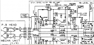
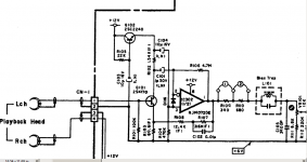
...Now, there's a problem with the Pioneer ct-93 design...the drain current and VDS looks like it works under the Miller plateau or very close to it ...and that means higher current noise, much less popcorn noise and much higher gm.
Attachments
Last edited:
- Home
- Source & Line
- Analogue Source
- BC550 BC560 Very low noise RIAA