Hi. I was changing capacitors of an old amp from the 70's and I damaged two diodes and broke them.
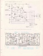
If I'm not wrong this is a class-AB amplifier in quasi-complementary configuration. I've attached the schematic.
The diodes I meant are named ZE 2 in the schematic. I've never came across that symbol before.
I found the datasheet of the ZE 2:
https://www.web-bcs.com/pdf/Jn/ZE/ZE2.pdf
It says Uf = 2.0v ... 2.3v
Is that Uf the voltage drop? Or is it a zener diode and that Uf means the breakdown voltage? I would say the former but I'm not 100% sure.
My diode didn't look as the ZE 2 at all. It looked like a old silicon diode. Black and a bit larger than a 1N5817.
After some research and read about the Baxandall diode I would say that the symbol in the schematic means "three diodes in series". The voltage drop across the diode is 1.7v so the maths work here.
In my board there were just one diode per channel and not three. I could read 2V1 in the diode.
With my little knowledge I would say that I need a voltage drop around the 1.7v and I'm in business, but I wanted to share my thoughts just in case I'm wrong and hopefully to learn something.
Even if I'm right it feels weird that the schematic says 1.7 voltage drop and the specified ZE 2 diode has a 2.0 - 2.3 forward voltage...
Cheers!
Attachments
It is indeed three diodes in series, probably 1n4148 diodes judging by the voltage drop.
I have made them in the past.
Solder them as a cluster as they change voltage drop with temperature and if mounted on or near a heat sink, work best close together.
I have made them in the past.
Solder them as a cluster as they change voltage drop with temperature and if mounted on or near a heat sink, work best close together.
Most likely this is 3 diodes in one 'package'. Looks like 1 diode, but it's 3 diodes in series. The one you found is a Zener diode. Not the one you were looking for.
Here is case like yours:
Sansui G-7500, 2980 Driver, STV-3H Excessive current draw? | Audiokarma Home Audio Stereo Discussion Forums
Here is case like yours:
Sansui G-7500, 2980 Driver, STV-3H Excessive current draw? | Audiokarma Home Audio Stereo Discussion Forums
These are bias / thermal compensation diodes in series. Can be selected from conventional diodes, Schottky diodes and GE diodes. You can additionally include a resistor of tens of ohms and select to the desired current. Can be replaced with Ube multiplier. You can use transistors with connected B-C.
Last edited:
FWIW, that's not a Baxandall diode. A Baxandall diode would appear on the emitter of T7 to make the T7/T9 Sziklai pair act more like the T6/T8 emitter-follower pair.
What you have is just a bias spreader / temp compensation. A trio of 1N4148s would certainly be the easiest solution.
You could find an LED with the appropriate voltage drop. Not sure if it's temp compensation would be the same though....
What you have is just a bias spreader / temp compensation. A trio of 1N4148s would certainly be the easiest solution.
You could find an LED with the appropriate voltage drop. Not sure if it's temp compensation would be the same though....
The only problem with 3 silicon diodes (.6 v each) series, or a Red LED (2 v) is fitting them in the recess of the heat sink near the output transistors. The Peavey amps I own have a recess milled in the heat sink to specifically fit this DO41 part.
You can get around that by gluing 3 series 1n4148 or a red LED to the heat sink with heat conductive glue. About $20 a tube last time I looked it up.
Your "stabistor" zd2 may not be defective. They measure as open on DVM diode scales, at least the ones I own. One has to test them with a >4 v power supply series a resistor (say 4.7 k) series the diode with plus on line end. Then measure across the diode with a volt meter.
Last edited:
FWIW, that's not a Baxandall diode. A Baxandall diode would appear on the emitter of T7 to make the T7/T9 Sziklai pair act more like the T6/T8 emitter-follower pair.
What you have is just a bias spreader / temp compensation. A trio of 1N4148s would certainly be the easiest solution.
That's right
Ok. Thanks to all of you.
So that's not a Baxandall diode but bias / thermal compensation diodes.
Three 1N4148 in series might work.
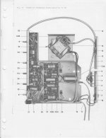
Yes, it's going to be tricky to put them in the heat sink though...Is it needed for this design? They definitely didn't do it. Just soldered them in the board like any other part. I've attached and picture where you can see the diodes between the two trimmers. Nothing fancy.
So that's not a Baxandall diode but bias / thermal compensation diodes.
Three 1N4148 in series might work.
Yes, it's going to be tricky to put them in the heat sink though...Is it needed for this design? They definitely didn't do it. Just soldered them in the board like any other part. I've attached and picture where you can see the diodes between the two trimmers. Nothing fancy.
Attachments
Naim also did that with a quasi-complementary output. They used un-ventilated cases, though, so the bias compensator would eventually reach thermal equilibrium.
Is the case of your amp ventilated?
Is the case of your amp ventilated?
Probably a STV3H like used on Pioneer vintage amps.
There is a thread on another forum regarding substitute candidates and there is also a 4 diode version used by Marantz.
STV3H-Y - stabistor Diode-Sanken STV3H STV-3HY | eBay
There is a thread on another forum regarding substitute candidates and there is also a 4 diode version used by Marantz.
STV3H-Y - stabistor Diode-Sanken STV3H STV-3HY | eBay
If the designers didn't put the diodes on the heat sink with output transistors, you don't have to. That controls output transistor heat better, but moving the stabistor there might cause oscillation, depending on how the board is laid out.Three 1N4148 in series might work.
Yes, it's going to be tricky to put them in the heat sink though...Is it needed for this design? They definitely didn't do it. Just soldered them in the board like any other part. I've attached and picture where you can see the diodes between the two trimmers. Nothing fancy.
I had taken plenty of pictures of this amp. In one of them I can clearly see the diode. It's a BZ 102.
By ventilated do you mean fans or something like that? Not at all.
By ventilated do you mean fans or something like that? Not at all.
No, I mean holes in the case. Here's a picture of Naim's (unventilated) case:By ventilated do you mean fans or something like that?
Attachments
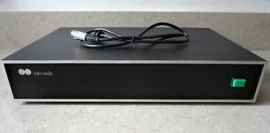
Oh,yes. Mine has holes at the bottom, right under the huge heat sink. The boards are mounted on this big heat sink. You can see the heat sink in the pics I attached in the first page.
I suppose they'd heat-soak to some degree from there, even with ventilation.
Seems a bit dodgy to me, but if it's been otherwise working since the 1970's then they clearly knew more than I....
Seems a bit dodgy to me, but if it's been otherwise working since the 1970's then they clearly knew more than I....
- Home
- Amplifiers
- Solid State
- Baxandall diode? AB quasi-complementary amp from 70' s