Charge, albeit slowly.
Perhaps more slowly than it self-discharges.
EDIT - I'd generally recommend 220 kΩ instead of 1,000 kΩ, too.
Unless you're creating an input well-matched to a piezo instrument pickup...
⋅-=≡ GoatGuy ✓ ≡=-⋅
Perhaps more slowly than it self-discharges.
EDIT - I'd generally recommend 220 kΩ instead of 1,000 kΩ, too.
Unless you're creating an input well-matched to a piezo instrument pickup...
⋅-=≡ GoatGuy ✓ ≡=-⋅
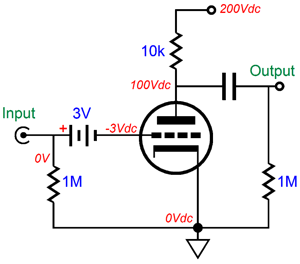
Connect it this way:
1. Input jack to the left end of the capacitor.
2. Connect the right end of the capacitor to a 220k Ohm to ground (or 1 Meg if you need that).
3. Connect the right end of the capacitor to the positive end of the battery.
4. Connect the negative end of the battery to the control grid.
5. If you need or want to use a grid stopper resistor, connect it between the negative end of the battery, and the grid. Connect the grid stopper right up close to the tube socket.
The Series battery works real well. The only time it conducts current is if you use a large enough signal to clip (draw grid current). And that charges the battery.
But who wants to clip a Hi Fi amp. Only clip a Guitar amp.
I have used this method for biasing input tubes, 2A3, and 300B tubes.
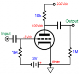
The circuit connection you showed above is always charging and always discharging the battery whenever there is a signal present.
And if the input cap is the least bit leaky, you will draw cap current even when the amp is off (if what drives the input connector has resistance to ground, or has an output that is at any voltage, +, -, or 0V, such as an IC output).
1. Input jack to the left end of the capacitor.
2. Connect the right end of the capacitor to a 220k Ohm to ground (or 1 Meg if you need that).
3. Connect the right end of the capacitor to the positive end of the battery.
4. Connect the negative end of the battery to the control grid.
5. If you need or want to use a grid stopper resistor, connect it between the negative end of the battery, and the grid. Connect the grid stopper right up close to the tube socket.
The Series battery works real well. The only time it conducts current is if you use a large enough signal to clip (draw grid current). And that charges the battery.
But who wants to clip a Hi Fi amp. Only clip a Guitar amp.
I have used this method for biasing input tubes, 2A3, and 300B tubes.
The circuit connection you showed above is always charging and always discharging the battery whenever there is a signal present.
And if the input cap is the least bit leaky, you will draw cap current even when the amp is off (if what drives the input connector has resistance to ground, or has an output that is at any voltage, +, -, or 0V, such as an IC output).
Last edited:
FWIW, there is an alternate method for battery bias. Place a stack of precharged NiMH cells between the cathode and ground. When such circuitry is powered on, the stack is subjected to a desirable trickle charging current. When such an arrangement is operated regularly, the NiMH cell stack lasts a long time.
Battery bias in the cathode "leg" eliminates the need for a DC blocking cap. in the grid "leg". That can be important when dealing with things like a phono cartridge.
Battery bias in the cathode "leg" eliminates the need for a DC blocking cap. in the grid "leg". That can be important when dealing with things like a phono cartridge.
Draw up a schematic as per the connections listed in post # 3.
Then:
Connecting the battery + from the junction of signal and the top of Rg, and the battery - to the grid does not put any current into a phono cartridge.
Not unless the tube grid draws its own current, that is a bad tube, and should be replaced. There is no capacitor required.
A 1.5V battery that biases a 12AX7 is not going to draw grid current when the small signal from the phono cartridge goes positive.
Records do not accelerate the needle at a rate of 200cm/sec.
System, System.
Last edited:
Records do not accelerate the needle at a rate of 200cm/sec.
Obviously not, because that's a speed, not an acceleration. 🙂
Maybe but I see 2 not too small problems:Connect it this way:
1. Input jack to the left end of the capacitor.
2. Connect the right end of the capacitor to a 220k Ohm to ground (or 1 Meg if you need that).
3. Connect the right end of the capacitor to the positive end of the battery.
4. Connect the negative end of the battery to the control grid.
5. If you need or want to use a grid stopper resistor, connect it between the negative end of the battery, and the grid. Connect the grid stopper right up close to the tube socket.
The Series battery works real well.
* you need 1 battery per grid. So two for stereo.
* whole battery and its wiring is floating and connected to a very high impedance, very high gain circuit ... did I say Hum/Buzz/RF magnet?
Besides being proof of snobbery to design using a 1920´s circuit which was obsolete in the 30´s. 😎
I thought more or less the same. We are going back a century ago.Besides being proof of snobbery to design using a 1920´s circuit which was obsolete in the 30´s. 😎
So… lets go back to the original idea, then.
A battery negatively biasing the grid via a 220 kΩ resistor. Granted, the battery will eventually die of old-age and gentle grid load.
NOTE that ordinary alkaline cells do not have really long-term packaging seals, so that when they leak, they create their own kind of disaster. We really are better served by tiny 'coin' batteries in this regard. They never leak, in my fairly long life's experience. The current draw is so low, that one can also use very tiny ones (addressing another poster's concern for larger-can-environmental-noise-pickup opportunities)
Anyway.
Moving right along.
Happy COVID–19 Awareness day!
⋅-=≡ GoatGuy ✓ ≡=-⋅
Last edited:
Am I missing something - a cathode resistor + cap. Must be missing the point, were caps were hard to make large in those days.
The Next Generation of Batteries Could Be Built by Viruses | WIRED
The Next Generation of Batteries Could Be Built by Viruses | WIRED
Last edited:
[1] Yes — in the “old days” making larger value capacitors was expensive and hard.
… before 1927, there were no foil-paper-foil coiled capacitors, electrolytic or otherwise. At first, capacitors were 'dry paper' types; then mineral oil was found to make paper far better as a diëlectric. But getting over 1 µF was hard and bulky. With borax-type electrolytes and well-impregnated paper, Aluminum-paper-copper was first used. Then as aluminum prices came down, Al-p-Al. And thus the electrolytic large-value revolution came to be.
[2] The nominal shortcoming of a R+C cathode 'bias' design is that the operating point can vary substantially with a relaxation time constant of R⋅C, as the nonlinear amplification of a valve with higher input will change the mean anode current outside the quiescent (no signal) value. R+C's voltage is an average of that imposed by mean anode current.
[3] And bulk was the other problem. The original electrolytics could be fairly high values (in the day), but in order to keep them from drying out or leaking when 'upside down', a fair amount of interlocked seals and insulating hermetic methods had to be deployed. Hence, the advent of the large “aluminum can”, multisection capacitor for power supply applications. Expensive at the time.
The point tho' was with the near-zero current flow of a grid-bias voltage source, the almost-free expense of a conventional “dry cell” which would last years and years … had its application obviously set.
⋅-⋅-⋅ Just saying, ⋅-⋅-⋅
⋅-=≡ GoatGuy ✓ ≡=-⋅
Mark Tillotson,
You caught me on that one.
I meant 200cm/(sec squared).
The idea was simple, 1.5V negative battery bias, 12AX7, and a signal from a phono cartridge that was hardly ever going to approach 1V peak.
(given an average phono cartridge spec of 5mV out at 5cm/(sec squared)).
Better?
You caught me on that one.
I meant 200cm/(sec squared).
The idea was simple, 1.5V negative battery bias, 12AX7, and a signal from a phono cartridge that was hardly ever going to approach 1V peak.
(given an average phono cartridge spec of 5mV out at 5cm/(sec squared)).
Better?
Last edited:
..would the grid leak current tend to charge or discharge the battery .
For good negative bias, the grid current is too small to matter to any battery.
Into the mid 1930s there were grid batteries half the size of a pea. These worked for decades, finally drying-out from cheap seals. Modern hackers drill to inject a micro-drop of water, and they work fine again.
Aside from the cost of caps, older heater-cathode construction used in low level stages could hum bad; a solid-grounded cathode was good defense, 100+uFd caps were not yet practical/affordable. (Telephone company had them, but they planned for 50 years out.) Without fat caps, clean negative supplies on wall-power was problematic. The grid battery was an excellent answer.
Your scheme will last until the battery dies of old age. Dries-up, leaks, or eats all its Zinc. For non-special types, 1 to 4 years.
Personally, I prefer to use the battery in series with the signal when I use battery bias... It will never discharge in theory. It's a 6DJ8 if you were wondering...
Last edited:
For the special case of a phono input, both input jack sleeves ("grounds") can be connected together and floated from signal ground by the battery's voltage. Cartridge loading needs to stay across the input jacks, and all of the wiring from tonearm to phono input floats at battery voltage. I like to mount the battery outside the case, next to the input jacks.
All good fortune,
Chris
All good fortune,
Chris
kodabmx,
Thanks for drawing up the schematic!
Now people can see the concept of what I was talking about.
Change tube type, battery voltage, input resistor, output capacitor, plate resistor, and output resistor to suit your application.
After I mount the battery, I measure the capacitance of the battery to ground, to verify that it is low enough capacitance so that it does not affect the circuit operation.
Last edited:
Personally, I prefer to use the battery in series with the signal when I use battery bias... It will never discharge in theory. It's a 6DJ8 if you were wondering...
This is dangerous practice. How will you keep the tube in its design range with ageing, and changing new tubes? There's nothing to prevent cut-off or runaway.
The cathode resistor//cathode decoupling cap at least gives a reasonable stabilization of the operating point against ageing/changes.
Jan
This is dangerous practice. How will you keep the tube in its design range with ageing, and changing new tubes? There's nothing to prevent cut-off or runaway.
The cathode resistor//cathode decoupling cap at least gives a reasonable stabilization of the operating point against ageing/changes.
Jan
THat's a fair point.
However, I also think it is a bit over-sold.
Many of us have come to embrace 'fixed bias' solutions for all sorts of valve-stage applications. LED bias (series, ground-to-cathode) is a more-or-less fixed bias solution. Results in exactly the same potential as you surmise.
Actual 'fixed bias' negative power supplies. Very easy to cobble together from valve heater A/C, it turns out. Next-to-zero current draw means that electrolytic capacitors can be eliminated for smallish ceramic jobs, or polypropylene. 3.3 µF to 6.8 µF is usually quite sufficient.
Your point tho' remains. RK cathode resistors, either with or without A/C-AKA-signal bypassing using a sufficiently large capacitor, at least also adjusts the operating point as the valve-in-question ages. One might even go further, and set up a low-voltage constant-current device as a 'super resistor' (but which definitely requires the capacitor bypass!).
In any case, simple is better.
Today, or more to the point, any time since 1965 or so, compact, high-reliability small-can, low-voltage electrolytic capacitors have become mighty inexpensive. The net of that is doing the RK || CK route is cheap, easy, self-adjusting, and just fine.
Using an eensy-weensy hearing aid battery, in series with signal as shown in the above diagrams, is just as valid, in the case where the designer / experimenter is wishing to implement fixed bias an old-fashioned-yet-new way.
I don't really think that 'valve runaway' or operating point variance is the driver. Or at least, if it is, then “valves age, valves die, that's what they do” isn't much changed. No real danger, per se.
⋅-⋅-⋅ Just saying, ⋅-⋅-⋅
⋅-=≡ GoatGuy ✓ ≡=-⋅
The plate loading resistor limits current. For the ultra paranoid, a constant current source does an even better job.This is dangerous practice. How will you keep the tube in its design range with ageing, and changing new tubes? There's nothing to prevent cut-off or runaway.
Sure. Assuming that the anode is at half supply, the max runaway current is twice the operating point current, so this is automagically limited.
Of course at that point the tube also ceases to operate as intended.
Jan
Of course at that point the tube also ceases to operate as intended.
Jan
- Home
- Amplifiers
- Tubes / Valves
- Battery bias question