Hello all
My name is Randy. I have been floating around the forum for a while. Recently, I started work on a pair of desktop speakers using drivers without proper specs. Only relevant info supplied were power, dimensions and a response down to 32hz. I asked for help on the forum, and a number of folks helped me work out some viable options with enclosures to try these out with. One of the directions was a TL of around 20 odd litres. Along the discussions, I ran various iterations of the model in CAD to visualise what the work file would look like. During the course, I noticed that I had created a template to allow these quick changes and its implications. This template would not have been possible without folks taking an interest and educating freely and being generous with their time and expertise. I found this to be the case with both commercial and enthusiast members of this forum
Allow me to share this template back to everyone. I'll be glad if this is of use to you to either easily make boxes for messing around or develop to your commercial boxes. The template will be able to assist you to create not only sophisticated speaker boxes but anything really. I will be using this for making a tube power amplifier chassis too
I call this particular implementation of the stepped tunnels the "Bassinga Flatwounds". Please mention this name with your work, so people may treat my misconceptions kindly 🙂

The system
This is based around a 3D model using FreeCAD. The template allows easy manipulation of all fields to a novice with CAD to alter required areas. Base model is for a 6.5" Pioneer coaxial driver that I am set to trail. The model can be scaled down and 3D printed or CNC'ed for tiny format speakers. My print bed is 40 x 40 x 40 cm, so I have the real estate to print my full box should I wish. This does take a while even with a 1 mm nozzle and fast settings, as well as material costs. This template will help solve these issues and I will show a tutorial in a future instalment once I am ready to proceed with my desktop TL build
For the moment, I am curious to sees how it prints. I have another pair of unknown 3" full range speakers with the only info being 30wrms and 8 ohms printed on the back. This will be a test for the comprehensive tuning abilities that my CAD template offers pre- and post-printing. This is for another future instalment
Template features
Full or semi prints
Model is converted to a building jig that ends up as decorative trim for boxes too large to print whole
Simple build process that can used already prepared flat material like finished floor planks as well as foam and foam core and the usual ply and MDF. Just about any suitable material can be used
The jig takes care of all the assembly work and removes the need for making wooden box edges look good
Some glue, a screwdriver and a drill are all the tools needed to assemble the box to result in a commercial level finish
Speaker workshops can adjust to their requirements and sell kits (please mention cab name)
Adjustments can be made to the template as well as to already made boxes, the tunnels can be inserted with all sorts of things to change tapers and such as well as stuffing due to the easy access nature inherent in the design
In the next instalment, I will show how to navigate the template and carry out changes. Do not hesitate to point out any mistakes. If any CAD sharks want to assist, go for it 😀
The zip file contains the FreeCAD 3D template
Let's keep this thread to the construction and assembly discussions and the audio discussions to the original thread now renamed and linked below
https://www.diyaudio.com/community/threads/desktop-tl-template-audio-discussion.396170/
Thanks and regards
Randy Bassinga

My name is Randy. I have been floating around the forum for a while. Recently, I started work on a pair of desktop speakers using drivers without proper specs. Only relevant info supplied were power, dimensions and a response down to 32hz. I asked for help on the forum, and a number of folks helped me work out some viable options with enclosures to try these out with. One of the directions was a TL of around 20 odd litres. Along the discussions, I ran various iterations of the model in CAD to visualise what the work file would look like. During the course, I noticed that I had created a template to allow these quick changes and its implications. This template would not have been possible without folks taking an interest and educating freely and being generous with their time and expertise. I found this to be the case with both commercial and enthusiast members of this forum
Allow me to share this template back to everyone. I'll be glad if this is of use to you to either easily make boxes for messing around or develop to your commercial boxes. The template will be able to assist you to create not only sophisticated speaker boxes but anything really. I will be using this for making a tube power amplifier chassis too
I call this particular implementation of the stepped tunnels the "Bassinga Flatwounds". Please mention this name with your work, so people may treat my misconceptions kindly 🙂
The system
This is based around a 3D model using FreeCAD. The template allows easy manipulation of all fields to a novice with CAD to alter required areas. Base model is for a 6.5" Pioneer coaxial driver that I am set to trail. The model can be scaled down and 3D printed or CNC'ed for tiny format speakers. My print bed is 40 x 40 x 40 cm, so I have the real estate to print my full box should I wish. This does take a while even with a 1 mm nozzle and fast settings, as well as material costs. This template will help solve these issues and I will show a tutorial in a future instalment once I am ready to proceed with my desktop TL build
For the moment, I am curious to sees how it prints. I have another pair of unknown 3" full range speakers with the only info being 30wrms and 8 ohms printed on the back. This will be a test for the comprehensive tuning abilities that my CAD template offers pre- and post-printing. This is for another future instalment
Template features
Full or semi prints
Model is converted to a building jig that ends up as decorative trim for boxes too large to print whole
Simple build process that can used already prepared flat material like finished floor planks as well as foam and foam core and the usual ply and MDF. Just about any suitable material can be used
The jig takes care of all the assembly work and removes the need for making wooden box edges look good
Some glue, a screwdriver and a drill are all the tools needed to assemble the box to result in a commercial level finish
Speaker workshops can adjust to their requirements and sell kits (please mention cab name)
Adjustments can be made to the template as well as to already made boxes, the tunnels can be inserted with all sorts of things to change tapers and such as well as stuffing due to the easy access nature inherent in the design
In the next instalment, I will show how to navigate the template and carry out changes. Do not hesitate to point out any mistakes. If any CAD sharks want to assist, go for it 😀
The zip file contains the FreeCAD 3D template
Let's keep this thread to the construction and assembly discussions and the audio discussions to the original thread now renamed and linked below
https://www.diyaudio.com/community/threads/desktop-tl-template-audio-discussion.396170/
Thanks and regards
Randy Bassinga
Attachments
Navigating the template
Open the template in FreeCAD and save as a new file named after your project. Now the template can be messed with without messing the template. It helps to keep the original open in the background for reference
On the left there is a list in the white sections. This is the list of all the dimensions that make the box shown on the screen

Template tips
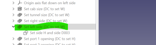
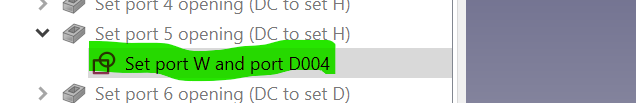
(DC to set) double-clicking on it will bring up a dialogue box with some numbers selected. Change this field to change the dimension
A little arrowhead means there is a sketch inside that can be adjusted by clicking on the arrowhead, then double-clicking on the sketch name
Cabinet features are in numbered queues on the list
YouTube tutorials demonstrate how to zoom around the object. In this template, the speaker box is laying flat on it left side
Next time I'll introduce the table used for getting the numbers to enter into the fields in the list
Thanks and regards
Randy
Open the template in FreeCAD and save as a new file named after your project. Now the template can be messed with without messing the template. It helps to keep the original open in the background for reference
On the left there is a list in the white sections. This is the list of all the dimensions that make the box shown on the screen
Template tips
(DC to set) double-clicking on it will bring up a dialogue box with some numbers selected. Change this field to change the dimension
A little arrowhead means there is a sketch inside that can be adjusted by clicking on the arrowhead, then double-clicking on the sketch name
Cabinet features are in numbered queues on the list
YouTube tutorials demonstrate how to zoom around the object. In this template, the speaker box is laying flat on it left side
Next time I'll introduce the table used for getting the numbers to enter into the fields in the list
Thanks and regards
Randy
Attached to this post is the table used to pull the numbers for the tunnel openings
This is a blank template. It can be used to break a pipe down to 6 segments using the mouth opening, vent and length as input data. Open the template and save as a suitable name for your project to preserve the original
Next will be a tutorial on a box for a small driver of 4" or under. We will start at a 80hz tuning on the pipe length. This will be a test box to find a suitable driver for my daughters mini desktop studio. I will be first testing a pair of Pioneer 4" coax. These speakers claim a 35hz extension but comparing physical properties with other similar drivers show that it might be a bit optimistic. The tutorial will cover creating the box at 80hz first and doing listening tests and measurements. Then increasing tunnel length on the box already made in around 5 to 10hz steps to optimise the box with more listening and tests. This 80hz cab can be easily drawn out to the template default of 34hz " after making the initial box
If anyone has a particular driver in mind, then please post the details in the separate discussion thread linked in the original post
Declaration
I have very little experience with speaker audio modelling. This template came about as I learned to do each step in FreeCAD, I am new to this type of CAD with only experience being with boat design porgies. It will be awesome if someone took charge of all the audio modelling for this tutorial. My strong point is solutions for unique and unusual construction process and technical drawings and such picked up through boat building, joinery, neon signs and fishing tackle manufacturing businesses
Thanks and regards
Randy
Attachments
Adapting to a smaller driver tutorial
The tunnel cross-section is rectangular. To make the box slim, I have chosen the driver's cutout size as the cab internal width and this number will be used in all the fields that run the width of the cab internally
My numbers for the tunnels are 56.8cm2 for the mouth and 19cm2 for the vent. The cab internal width limit is 106 mm based on the driver cutout. The tapered pipe length at 80hz is 84 cm
Segment length = 84 cm / 6 segments
Segment length = 14 cm
Let's load the table template and save it as 'flatwounds 4 inch 80hz'
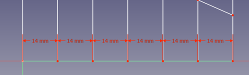
Click on the green line and first dot as shown, and they will turn to green. Click on the insert length icon on the toolbar and set to 14 mm. The table does not care about the units as long as they are the same. We will imagine that we are reading 140 mm. If we enter 140 mm, then the table will shoot out really wide and be a pain to handle

Repeat dot to dot to the last dot

Use the height icon to set the first and last vertical lines. These are the mouth and vent worked out in offline audio modelling. The table should turn a happy green and is ready for conversion. Set the length of the second vertical line, and the table will get angry. It will show a length, that's the opening area of port two. Cancel to make table happy again

Save the file and let's work out the tunnel heights
Now make a list of tunnel cross-sections
Opening height = opening area 56.8 cm2 / cab internal width 106 mm
Opening height = 54 mm
Vent height = vent area 19 cm2 / cab internal width 106 mm
Vent height = 18 mm
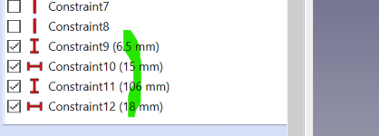
Change the first and last vertical lines to 54 mm and 18 mm, like so. Double-click on the numbers to edit them

Now the vertical lines will show each port height instead of area, and you can get those numbers by making the table angry at each vertical line
Write down all the numbers in order 1-6 for the tunnel heights and in the next instalment, we will start adapting the cab template with these numbers
Thanks and regards
Randy
The tunnel cross-section is rectangular. To make the box slim, I have chosen the driver's cutout size as the cab internal width and this number will be used in all the fields that run the width of the cab internally
My numbers for the tunnels are 56.8cm2 for the mouth and 19cm2 for the vent. The cab internal width limit is 106 mm based on the driver cutout. The tapered pipe length at 80hz is 84 cm
Segment length = 84 cm / 6 segments
Segment length = 14 cm
Let's load the table template and save it as 'flatwounds 4 inch 80hz'
Click on the green line and first dot as shown, and they will turn to green. Click on the insert length icon on the toolbar and set to 14 mm. The table does not care about the units as long as they are the same. We will imagine that we are reading 140 mm. If we enter 140 mm, then the table will shoot out really wide and be a pain to handle
Repeat dot to dot to the last dot
Use the height icon to set the first and last vertical lines. These are the mouth and vent worked out in offline audio modelling. The table should turn a happy green and is ready for conversion. Set the length of the second vertical line, and the table will get angry. It will show a length, that's the opening area of port two. Cancel to make table happy again
Save the file and let's work out the tunnel heights
Now make a list of tunnel cross-sections
Opening height = opening area 56.8 cm2 / cab internal width 106 mm
Opening height = 54 mm
Vent height = vent area 19 cm2 / cab internal width 106 mm
Vent height = 18 mm
Change the first and last vertical lines to 54 mm and 18 mm, like so. Double-click on the numbers to edit them
Now the vertical lines will show each port height instead of area, and you can get those numbers by making the table angry at each vertical line
Write down all the numbers in order 1-6 for the tunnel heights and in the next instalment, we will start adapting the cab template with these numbers
Thanks and regards
Randy
Attachments
Tunnel heights list
Port 1= 54 mm
Port 2 = 48 mm
Port 3 = 42 mm
Port 4 = 36 mm
Port 5 = 30 mm
Port 6 = 24 mm
Port 7 = 18 mm
Tunnel length 6 x 140 mm
Driver cutout 106 mm
These are the numbers that set the cab for the tutorial for the 4" driver. We will adapt the template step by step. This will end up a fairly small and narrow cab with 5 internal braces. I am inclined to use 6 mm as the material thickness unless there are strong arguments for going thicker
If anyone has any projects coming up for a similar cab and are interested in adapting the template to your use, now would be a good time to join this thread with your project particulars and get started. It will be a great chance to demonstrate the ways this template can flex its muscles
Thanks and regards
Randy
As can be seen in the attachments below, all the parameters can be edited and the template formed to just about any 6 segment volume, but this is not how to exploit the template. These are tools to use to extract numbers and get a visual on shape. There are a zillion steps to get to the end result, which is the jig/trim. Once the model is fully formed, it is sliced using a rectangle to create separate files for each jig area. This is the work that I have already done in the background over the last couple of days and extracted the numbers for the jig only. Since print speeds are slow and material costs are high, further manipulation of the template will be at member request
The template is the one to use for a fully printed style and the jig sub templates are for using pre-cut panels to minimise print time and material, and this will be the means to create the test cases for the 4 and 6.5" coax. I'll use the numbers extracted from the template to create the trims and present them next along with editing instructions. These trims not only align the panels, but also provides an engineered structural and mute function. The material to use is PETG or PLA+ with surface treatment
The template is the one to use for a fully printed style and the jig sub templates are for using pre-cut panels to minimise print time and material, and this will be the means to create the test cases for the 4 and 6.5" coax. I'll use the numbers extracted from the template to create the trims and present them next along with editing instructions. These trims not only align the panels, but also provides an engineered structural and mute function. The material to use is PETG or PLA+ with surface treatment
Attachments

This is another project halted due to FreeCAD instability. Over the last few months things have also been hectic with pregnancy, renovations and new baby arrival. In that time, I have been thinking about how to beat FreeCAD, and I have won. Finally found a way to create a template that won't crash it. Another positive is migrating the design away from wood based products due to foam performing better as a speaker cab material
Changes
Tunnel length, SD and ratio can be used from HR and cab tuned to those numbers without editing the FreeCAD template for drivers to 6.5" and some larger drivers can be fitted with a throat adaptor
Template can be edited if needed
Based on foam sandwich construction, the tutorial covers build examples with a 6.5" coax driver, a 6.5" sub driver and a two-way. Everyone can learn to use this construction method from these three builds. First, the example will show how to use the template for prototyping followed by locking in a design and completing it to home use duty using XPS and also to offshore F1 powerboat racing levels using PVC foam
Oh, the template is suitable to quickly set up and tune the cab to the driver of your choice and your HR expertise or building the base design using the drivers in the example and tuning that to your liking
I have all the materials on hand or coming in and over the next few weeks I'll show how to use the template and complete the first box. Before that, I need to assemble my CNC/laser router, as the design is either cut at home or ordered from a CNC place. It will be interesting to see how the hobby size machine deals with it, and such a machine could be worth considering for anyone who tinkers like this
It can also be hand cut if you are good with tools, and it's only cutting foam so not too difficult
Last edited:
- Home
- Loudspeakers
- Full Range
- Bassinga 'Flatwounds' desktop TL template and tutorial