My WinISD simulations suggested me rather higher port/filter frequencies to attain a flat response, but maybe I made sth. wrong. I added the WinISD results which give me the boost by the filter and the box/port resonance and the given frequency response for the chassis.
Maybe I interpreted the curve wrong but for a flat response, I had to use filter/port freq. between 60 and 70Hz and a q higher than 2 for the filter. I'm not sure if a higher q impements possible drawbacks, filters is a still new thing to me.
Cone excursion would also be quite bigger if I set the port frequency and the filter that much lower than the chassis' resonance.
Visaton: I thought of the Visaton FR10-8, they have a nice response for the price (I just saw them for 4,05 Euro at Farnell, normally they cost about 11.-) exept two peak I'd maybe have to flatten out.
The Visaton FRS8 got many nice comments about it's sound too (and it's curve is very flat), but it's only 82dB loud at 1W and it will be even more difficult to get some bass out of it.
I'm not that sure anymore because they have a high (95Hz) resonance. Anyhow, simulation looks not that much worse than for the SPH-60x.
But now, I'm keen on building something!
I'll immediately make a "to do" list, so I can listen to those speakers soon!
Your help with the filter is much appreciated, you helped me a big step further! 🙂
Best wishes,
Dominique
TAKE THE 4 OHM VERSION of the FR10!
They have different parameters and model much better in smal BR boxes.
I have used those in a 2.9 liter BR box and the bass is very reasonable.
I use them unfiltered and they are a little forward in the lower midrange then. If your source is able to eq. you can compensate for this without a filter but even without they sound nice.
The FRS-8 is nice sounding but difficult to model in BR (almost impossible). They are better off in a closed box
Oh, that looks great!
Nice woodwork! I'm still indoubt (as you are 🙂 ) if I will be able to make my box look as good.
I'll check for the 4Ohm chassis data.
But in general, I'd prefer to go for a 8Ohm speaker as they're easier to handle for the amp, especially for the planned active version to take away with a tiny (and weak) Class-D amp.
What do you mean when you say that this chassis is difficult to model in BR?
Do you mean it's difficult to predict the results and the result will differ a lot from the software simulation?
What port frequency did you use? Let me guess from looking at the ports... 50 o 60Hz?
Cheers,
Dominique
I've used them also with an 41Hz Amp3 which is a small classD amp and that functions marvelous. The amp is stronger than the speakers can handle. The class D amp has no problem in driving them and I think it is only 2*15w into 4ohms or 2*8w into 8ohms. (So you get the most out of your amp as wel)
If you try to model the 8ohm version in a small BR box there will be lots of bumps and dips. The 4ohm version models smoother.
I wanted them to go relative low in the smallest box where I would get some bass out of them, hence the 2.9 liter version. Due to stuffing I calculated the effective volume with 3 liters tuned to something just below 70 Hz ( I think it was 68 or so).
My box is 20*20*11.8 made out of 12mm hardwood and multiplex. I've made some braces to stengthen the box and to overcome the relative thin walls.
The 11.8 cm for the front is used because the front had to be relatively small and the 11.8 cm is a standard size at the local "Bauhaus" in 12mm thick.
Note that there would be space for a small tweeter like a peerles NDT-53 or so. I was not sure whether it would work like I wanted to so I kept the option open to change the chassis to a Monacor SPH100KEP with a small tweeter.
Hi,
The problem with the 8 ohm version is high Qts, 0.77 compared to the 4 ohm 0.56.
Theory is one thing, finding a driver with the right parameters so you can use it another.
Ideally we want something around 0.45 with low Vas.
The 4 0hm Visaton models fairly well in a 2 litre box with a port
tuning of 55Hz and high pass filter with f = 55Hz Q=2. The mild
1.3dB peaking at 165Hz will be fairly irrelevant after you have
added EQ for Baffle Step Compensation (active again!).
Bass power handling will be fine for a 15W 4ohm amplifier.
No point making the box bigger than 2 litres.
Also note there should be some taper to the bass as above.
Trying to be flat to cut-off will sound boomy and one-note.
🙂/sreten.
Well, I've tried them in 1,7 liters and there is a significant difference in bass responce with 3 liters.
I've not used Bassboost or a transform so maybe that could make a difference.
I've not used Bassboost or a transform so maybe that could make a difference.
Hi,
using 3 litres decreases the hump at 165 hz and
reduces the boost needed at 55Hz from 6dB to 3dB.
The two responses for the two cases are almost identical.
Without the boost the 3 litre is obviously superior for bass.
🙂/sreten.
using 3 litres decreases the hump at 165 hz and
reduces the boost needed at 55Hz from 6dB to 3dB.
The two responses for the two cases are almost identical.
Without the boost the 3 litre is obviously superior for bass.
🙂/sreten.
Please, sreten, (or whoever can help) could you clarify this for me:
This is the way I thought the whole thing goes:
Entering the necessary parameters for the chassis and the box in WinISD.
Then it gives me a curve which indicates how the box (with port or other included parameters) influence the frequency response.
Then, I add (well, I calculate some reference in my head) the curve to the fequency response from the manufacturer for the driver (or my own if I measured).
Is this wrong?
I just wonder it is, because from this procedure, I receive a pretty flat response only when I use port/filter resonant frequnecies in the region of 75Hz (for 3.5litres of volume) And you tell me something much lower!
Cheers,
Dominique
Sreten,
I would also like to know how to implement such a bassboost, I assume it will need active filtering at the input of the amplifier. However I would need a circuit that is very small as my amplifier is enclosed in a 32mm dia copper tube of 13 cm long
I would also like to know how to implement such a bassboost, I assume it will need active filtering at the input of the amplifier. However I would need a circuit that is very small as my amplifier is enclosed in a 32mm dia copper tube of 13 cm long
indoubt said:Sreten,
I would also like to know how to implement such a bassboost, I assume it will need active filtering at the input of the amplifier. However I would need a circuit that is very small as my amplifier is enclosed in a 32mm dia copper tube of 13 cm long
The details are in this post :
http://www.diyaudio.com/forums/showthread.php?s=&threadid=75974
🙂/sreten.
Dominique said:Please, sreten, (or whoever can help) could you clarify this for me:
This is the way I thought the whole thing goes:
Entering the necessary parameters for the chassis and the box in WinISD.
Then it gives me a curve which indicates how the box (with port or other included parameters) influence the frequency response.
Then, I add (well, I calculate some reference in my head) the curve to the fequency response from the manufacturer for the driver (or my own if I measured).
Is this wrong?
I just wonder it is, because from this procedure, I receive a pretty flat response only when I use port/filter resonant frequnecies in the region of 75Hz (for 3.5litres of volume) And you tell me something much lower!
Cheers,
Dominique
Hi,
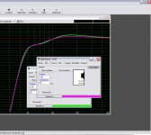
you ignore the manafacturers curve in the bass,
response is derived from parameters.
in WinISDpro you add the boost using the
"peaking 2nd order highpass" option.
This will give you the bass response.
shown are the curves for the figures I stated previously.
🙂/sreten.
Attachments
Ok, so how I thought the procedure went was wrong!
But with the rest of the WinSMD simulation, I didn't have any problems, it is pretty straighforward!
I'll go adapting my simulations now... 🙂
Thanks again, sreten!
Dominique
But with the rest of the WinSMD simulation, I didn't have any problems, it is pretty straighforward!
I'll go adapting my simulations now... 🙂
Thanks again, sreten!
Dominique
indoubt said:However I would need a circuit that is very small as my amplifier is enclosed in a 32mm dia copper tube of 13 cm long
Do you have a picture?
Sounds interesting, that copper tube amp! 🙂
I don't know how much of that coppertube space is already used, but the filter circuit can be pretty small, the capacitor values aren't high.
Cheers,
Dominique
Hi,
the next area to address is baffle step compensation.
This is easily implemented again in the fedback loop using a RC
series combination in parallel with the higher of the gain setting
resistors, this resistor is also increased in value to suit.
The parallel value of the two resistors = previous gain setting value.
Centre frequency of the baffle step depends on the baffle width.
I recommend 3dB of BSC.
(they aren't going to be used on stands in free space)
It is easy to make this adjustable with a pot, if so, 0 to 6dB BSC.
Its also possible to include a passive treble control by using an RC
in parallel with the lower of the gain setting resistors, again 0 to 6db ?
🙂/sreten.
Dominique said:
Do you have a picture?
Sounds interesting, that copper tube amp! 🙂
I don't know how much of that coppertube space is already used, but the filter circuit can be pretty small, the capacitor values aren't high.
Cheers,
Dominique
Yep, I do:


The heatsink is rounded to the inner diameter of the copper tube so the whole housing can perform as heatsink.
The connectors on the back are critical, There is power in, Speaker left, right and input left and right. I couldn't use RCA's as you can imagine but used high grade micro coaxal connectors. The internal signal wiring is Silver micro coax and the power cables is 0.8mmSQ silver cable. The power capacitance is inside the tube and 16V 4700uF. The potmeter is at the front.
I can tell you that it is a close fit😎
The amp functions very well and has great sound. It is indeed better than a lot of the commercial available stuff. It has no problem driving my Seas monitors (main system) to levels that you do not want to listen to anymore.
I have not yet touched the supply caps on the board and the input caps, they probably will be tweaked in future.
I've given the amp to a friend which normally uses tube amplifiers only and he was amazed about the amp driving his huge fostex horns. The amp is very silent (hiss, humm etc.) It was not as good as his expensive tube amp but it was surprisingly close😀
@sreten
baffle step compensation: that's a goof hint!
I think I'll wait for the box to be built with the speaker in it and then measure it's frequency response. Maybe the baffle step peak is casually where the chassis' response has a dip 🙂
I don't know... But I think I'll then see where corrections are the most urgent.
I've downloaded a rather new program called Boxsim which already has most of the visaton chassis parameters in it, and which also simulates the baffle's influence. I've just to figure out a last thing to make it work correctly.
@indoubt
Your circuit looks smaller that the one on the 41Hz site. But I only took a quick look. I'll go back as those amps seem interesting!
The thing is just I'll have to decide what to build next, I'm thinking of too many projects at the same time and I'm not experienced enough to handle them all at the same time...
I like your case and cooling! It's very special!
In any case, you still sem to have some space to include that active filter if you use small parts.
Cheers,
Dominique
Sreten, now I see what you mean! 🙂
I didn't think the baffle step would have such an impact!
Both, Boxsim (www.boxsim.de, but it's in german) and Edge (from Tolvan.com) show me the big and very wide peak because of the baffle.
I couldn't find any data on how much this could be damped (probably only a bit) by using damping material, like some soft fabric on the baffle.
Now I'll try and simulate a few circuits I found in a book to compensate for the baffle's influence.
Cheers,
Dominique
Hi,
the effect of BSC depends very much on the size of the driver you
choose in a simulator, I've heard in practical terms if the driver is
more than half the baffle width BSC is relatively smooth.
In most commercial 2 way speakers the bass units inductor is
oversized and comes in early to effect baffle step compensation.
As I said before you can mod the the feedback resistors to give
you around 4dB BS, a simple RC circuit will have a slope very
near what is required.
For some measured results of BSC, always good for a sanity check,
see : http://zaphaudio.com/
🙂/sreten.
Hi sreten,
thanks for the link with some more valuable info!
At the moment, I'm not advancing quickly, because while I work on the subject and learn new things, new "to do's" are added to the list each time... 🙂
It's nice to know you're still there and I promise to come back soon with most of my homework done, but probably some more questins also.
Cheers,
Dominique
Hi,
now I've assembled (err, only at my computer) the thing I thought you meant to compensate for the baffle step.
It could be about right for my box, and I'll leave fine tuning until I'll have assembled and measured the speakers in the housing.
Was it the circuit you were thinking of or did you mean something else?
Cheers,
Dominique
Attachments
- Status
- Not open for further replies.
- Home
- Loudspeakers
- Multi-Way
- Bass boost in portable active speakers?