Not easy to follow is it 🙂
With 3 volts on A and B that right hand NPN should be on as it gets base current via the 10k. The collector should be at close to zero... and it is not, you show 2.3 volt.
That is something to look at.
With 3 volts on A and B that right hand NPN should be on as it gets base current via the 10k. The collector should be at close to zero... and it is not, you show 2.3 volt.
That is something to look at.
 that is one problem fixed then.
Did we say that the 5 volt supply might be a limiting factor a while back. Once you account for the LED forward volt drops and all those diodes then there isn't much left to play with.
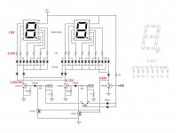
I can play with the supply voltage but when i increase it to make the LEDs brighter the AND gate stops working. According specs the LEDs should have a forward voltage of 2,5V but here they stay consistently at 1,8V at least for currents between 3 and 10mA. Could it be something with 1N4148 diodes? The first row is one diode per LED segment so the current is small. But the second row is one diode per digit and this varies up to 70mA. Still shouldn't be much should it?
Last edited:
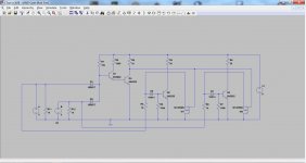
Although the simulated circuit appears to work flawless, I had no luck to confirm that in real life. So, I thought to simulate with pure resistive load in place of the LEDs that comes closer to the actual current and voltage drop. Then the simulation agrees with my prototype. Clearly, something is overloading the AND gate. Next step was to insert another driver -Q4. The -former LEDs- new loads are now R9/3/6. I'm happy to report it works like a charm this way! Do you see anything wrong with this approach?
Attachments
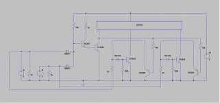
 that looks good. It's also giving a useful increase in the voltage needed to actually turn that stage on by adding another 0.6 volts or so which means it is easier to to turn off via the input diodes. It all becomes less critical.
Good 🙂
Nice! Mooly, I have not enough words to thank you! I have to order new PCB to build it neatly and hopefully return to share a fun and useful project.
I should have posted this about a month ago, alas DHL played wicked games with my PCBs... Anyway, I'm happy to report success! The final and more reliable version is attached.
As you might have guessed already, it is about a DAC display. So, I thought I should post it here Diode-Transistor Logic Display (for Wave IO)
As you might have guessed already, it is about a DAC display. So, I thought I should post it here Diode-Transistor Logic Display (for Wave IO)
Attachments
Last edited:
That's excellent and those boards in the other thread look really good. I'm pleased it all came together.
- Home
- General Interest
- Everything Else
- Basics on transistor drivers