You probably need to verify whether it has enough slewrate to do 20KHz at full power. 330pf is too big on this aspect.es.
It was dimensioned while doing AC Sweep.
Of course it is possible to reduce the value.
But I keep it at 330 pF.
I would say use 30MHz ft output devices and you could get away with a minimal compensation like 47pf.
The formula for slew rate in a capacitor is V/t = I/C. all in nominal form. Volt, seconds, Ampere and Farad. In this case with 10 pf for Ccb -
U/C = 0,5 mA/340pF gives 1,47v/us.
For 34 v t-t out it means max frequency full power out is 1,47/(34*2*3,14)MHz = 6,9kHz.
With a small capacitor in parallell with R15 and much smaller C6 a stable frequency of more than 100kHz ought to be reachable.
U/C = 0,5 mA/340pF gives 1,47v/us.
For 34 v t-t out it means max frequency full power out is 1,47/(34*2*3,14)MHz = 6,9kHz.
With a small capacitor in parallell with R15 and much smaller C6 a stable frequency of more than 100kHz ought to be reachable.
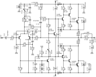
I myself is a fan of these type, I actually am playing with this one in sim I found the schematic from one of the threads here. It was mentioned that the original schematic was called Studio in Bulgaria. I made a version of my own using the standard EF, I've read that the Bryston type outputs (in the schematic posted) are known to be misbehaving.
🍻
🍻
Attachments
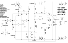

I worked a little on the circuit in post #40.(simulations)
DC offset at the output:
reduced by changing resistors R3, R4
clipping behavior:
terrible without D2, quite OK with 1N4007, good with BAT46.
gain margin 19dB
phase margin 71°
If C4(feedback) is increased to 270µF or more, the phase never becomes zero and you cannot read any value for gm.
pm is then displayed as 289°
Bias:
From 15-20 mA per output transistor the THD is acceptable.
Attachments
Last edited:

catd, you might like to put a resistor in the collector of T4.
Without it, T4 WILL die on overload and then kill T5, T7 & T9s in short order.
D2 prevents overdriving. But overLOAD will take out everything from T5 all the way to the output inductor. D2 or no D2, resistor in Q4 or no resistor in Q4. TIP35’s aren’t rugged enough to withstand even a momentary output short on +/-35V.
Yes, that is why I mentioned in #40:
The amplifier actually exists and with said protection, you can't kill it even if you short the output.Since there is no savety circuitry in the amp itself, it is powered by a stabilized supply with overcurrent protection/shutdown.
Last edited:
...since the late 1970s, in a circuit version shown in #40, but without D2. It's in daily use.The amplifier actually exists...
A regulated current limited supply is a solution for any amplifier. Whether it’s enough protection depends on the current limiting profile. How fast, at what current. Internal SOA protection on the amp itself can do more - allowing higher current at low VCE and reducing it into a short. If those were incorporated, overcurrent protection for T4 and T5 (ie, D2) is required. When activated, they would short the VAS collector to ground, which kills T5 if no limiting mechanism for it is employed. If the power supply does all the limiting, T5’s current is limited to whatever the base current of T7 tops out at when the supply goes into limiting. Probably only 10 or 20 mA. This is why you got away without D2. It still improves clipping behavior to have it.
to be exact, my used power supply switches off it's output voltage completely when the set max. current is reachedwhen the supply goes into limiting.
It must then be disconnected from mains (power switch) for about one minute until it resets.
I could have installed a reset button, but for some reason I left it out back then.
Last edited:
- Home
- Amplifiers
- Solid State
- Basic Power Amplifier Retro