

Lets try the simulation of the JLH at low supply voltage...
This is at 420ma bias current and a 6 ohm load. You can see it just fails to reach its maximum output and clips slightly at the top of the signal. At 8 ohm that disappears.

This is at 446 milliamps. It just manages to reach 5 volts.

This is at 420ma bias current and a 6 ohm load. You can see it just fails to reach its maximum output and clips slightly at the top of the signal. At 8 ohm that disappears.
This is at 446 milliamps. It just manages to reach 5 volts.
This amplifier is neither worth the effort nor the money. In fact, this is ancient junk for the fun of young people like the "my 1st DIY class A amplifier".
JLH was a great engineer, and appreciated sound quality as well. He did excellent work throughout his career.
https://en.wikipedia.org/wiki/John_Linsley_Hood
Thanks for the simulation info, Mooly. I wish my "el-cheapo" signal generator would produce a clean wave. Even when hooked directly to my (cheap) oscilloscope I can't seem to get a smooth wave of any type.
I'm afraid the phrase "you get what you pay for" applies to cheap electronics. Live and learn, I guess...
Happy New Year to everybody!
I'm afraid the phrase "you get what you pay for" applies to cheap electronics. Live and learn, I guess...
Happy New Year to everybody!
Good case example of previous thread.
Where using test signals from YouTube as source.
If a old signal generator has that much distortion.
Looks like Youtube at this point would at least give you a cleaner
sinewave. Even a phone app
Thousands of old lap tops with bad batterys
So likely stumble across a old lap top supply
one of these days for free. And test the circuit
on higher voltage. Fun board to have lying around.
Learning to solder is one of those oddities.
We all likely destroyed a tip or two in the beginning.
Just sitting the heat will oxide the tip quickly.
So utilize the sponge that comes with it.
Clean the tip between welds, and if leaving
it set while working. Bath it in solder so it
doesn't oxide while sitting on. It should
be shiny shiny shiny. Take a fresh start
with a new tip. Because heat transfer is important.
Sponge should be wet soon as you start and wipe
it every few welds.
Thanks for the simulation info, Mooly. I wish my "el-cheapo" signal generator would produce a clean wave. Even when hooked directly to my (cheap) oscilloscope I can't seem to get a smooth wave of any type.
For a single frequency you might be able to clean it up using a simple R/C - R/C filter. Maybe a picture of what you see on the scope. If the scope is a really cheap one you might be seeing issues there rather than from the generator.
(a 1kHz sine tone played at low volume through your amp should sound super 'smooth' and pure. Any harshness (caused by harmonics) at all is distortion)
It Is also really easy to make your own spot frequency test signals or even frequency sweeps using a PC and something like 'Audacity' which is free. You can create an MP3/WAV or whatever test file to play on anything suitable. You can also burn them to a CDR/RW
If you want a 1kHz pure sine test file to play with I can post one here 🙂
I suspect you will find that the kt1 variable resistor sets the mid point voltage of the output which should be at 1/2 the supply. 😉 But you need to check it does do that. The original circuit was seen as far too simple by some however it works. That largely due to the feedback and also considering hfe variations in the transistors used. He will have done that. The article mentions the main "problem" with the circuit. The gain of one of the output transistors does have an effect on distortion levels. Again he will have considered that. However this is with the original transistor types not 2N3055's. Those cropped up later. The JLH circuit I have seen using them is 15w and used a split supply. Other changes as well but JLH for personal use stuck with his original design.
Around the time the article came out one was knocked up in the electronics lab I worked in at the time. 2N3055's were around so these were used. Also other part changes based on ft, gain and power dissipation.
It wasn't hard to find a 2N3055 variant. This shows KT1 as I would expect and also KT2 that allows standing output stage current adjustment

I believe this is a Chinese variant, Similar to JLH's using these transistors

Note the adjust R5 comment - hence your kt1. The point that has to be considered when this style of output stage regulation is used is the power dissipation of TR3, the pot too.
Heatsinks. If one per amp as shown you will probably be ok at 10w 😉 but there is only one way to find out and the TR's will get hot. Probably too hot to touch other than briefly. Supply voltages for various loudspeaker impedances can be scaled from the original article. If a transformer supply is used VA rating needs considering. For instance say you used a toroid with a rating of 100VA, take that load all of the time it will run very hot. That thanks to Class A
Around the time the article came out one was knocked up in the electronics lab I worked in at the time. 2N3055's were around so these were used. Also other part changes based on ft, gain and power dissipation.
It wasn't hard to find a 2N3055 variant. This shows KT1 as I would expect and also KT2 that allows standing output stage current adjustment
I believe this is a Chinese variant, Similar to JLH's using these transistors
Note the adjust R5 comment - hence your kt1. The point that has to be considered when this style of output stage regulation is used is the power dissipation of TR3, the pot too.
Heatsinks. If one per amp as shown you will probably be ok at 10w 😉 but there is only one way to find out and the TR's will get hot. Probably too hot to touch other than briefly. Supply voltages for various loudspeaker impedances can be scaled from the original article. If a transformer supply is used VA rating needs considering. For instance say you used a toroid with a rating of 100VA, take that load all of the time it will run very hot. That thanks to Class A
I've wondered what I've actually installed (stuffed?) on the PCB's. As many have experienced, the transistors that were in the ziplock bag of parts with my kit were (faintly) labeled as 2N3055's. I'm afraid that I wouldn't know how to verify the authenticity of the transistors -- or anything else in the kit.
My latest basic question: To twist or not to twist wires -- does it make a difference sonically, or is it primarily for neatness? If twisting is advised, which wires should and which should not be twisted for the JLH design?
Thanks for your help. I'll upload a progress pic in a bit...
My latest basic question: To twist or not to twist wires -- does it make a difference sonically, or is it primarily for neatness? If twisting is advised, which wires should and which should not be twisted for the JLH design?
Thanks for your help. I'll upload a progress pic in a bit...
The good thing with the JLH is that it is not really fussy on exact transistor type as long as the output pair can handle the current. Verifying transistors is beyond the scope of most. You could test them up to their published limits and see if they survive but your JLH kit won't come close to that. If they were 2N3055 or 2N3772 or 2N3773 (all hefty power transistors from years ago) you would be none the wiser. Things like breakdown voltage, gain, Ft or transition frequency can also all be checked but there are many many transistors that would be very similar.
Also modern genuine production parts are often a long way removed from the original devices from decades ago in aspects such as gain and Ft and so checking is not always clear cut.
Twisting wires... erm... and I know many will have their own ideas on all this... is generally done to try and reduce radiated magnetic fields that (in audio circuits) can be picked up as hum by sensitive low signal level circuitry and this really applies to wires carrying AC current. Wires from a transformer in a power supply are one example. As you are using a switching supply that outputs DC none of that is relevant though.
I would say keep wiring short and neat, keep speaker wires away from input signal carrying wiring and keep the DC power wiring neat and running close to the chassis.
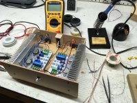
I thought I should post a pic of my little project (aka My First Amplifier). As I'm trying not to spend much, I made an "enclosure" out of wood. I can't believe how expensive enclosures are! I plan on getting some kind of perforated metal for a top, but it can wait...
Attachments
Very neat for a first build.
Just a stupid question: did you put thermal paste between the heatsink and the alu angle where the transistors sit on? Might not be a real issue as long as you run on reduced voltage but it could help.
Just a stupid question: did you put thermal paste between the heatsink and the alu angle where the transistors sit on? Might not be a real issue as long as you run on reduced voltage but it could help.
I'm sorry for my slow response to your question, Havoc. Yes, I did use thermal paste between the angles and the heatsinks. Although there was some "squeeze out", repeated handling (leading to messy hands) got me to wipe off any excess at the edges.
Thanks for your kind response to my build pic.
Thanks for your kind response to my build pic.
Put together a Chinese copy of JLH. What is the correct way to set the midpoint voltage? By symmetrical sine limit or half of the supply voltage?

The best way is to adjust for symmetrical clipping but you must do it into a representative load for it to be meaningful. Fwiw, asymmetric clipping will make no discernible difference to subjective maximum level, it would need to be off by a very large amount for that and so in practice around half supply is fine as a general setting.
- Home
- Amplifiers
- Solid State
- Basic JLH '69 amp build questions. Please excuse me for asking...