Hello Kristijan,kristijan-k said:Hello,
Here is also one example of Valve (ECC88/E88CC/6DJ8/6922)
Line Preamplifier that I found.
Does anyone tried it, and is there any comment on sound quality ?
It's a fairly typical SRPP implementation, just with a bit lower B+ than I would use. Probably sound quite nice, <i>depending</i> on the load it runs into. SRPPs can change their sound depending upon load conditions, and are only ever really optimised at one impedance. Personally, I don't like them for a number of reasons, especially excess gain with 6922s, but that's just my opinion, and I think you'll find a lot of dissent about that.
It's easy and simple to try. Give it a go and see what you think. You might really like it.
kristijan-k said:
Here is also one example of Valve (ECC88/E88CC/6DJ8/6922)
Line Preamplifier that I found.
Does anyone tried it, and is there any comment on sound quality ?
Looks like a cathode follower with suboptimal voltage drive.
I have tested in the past several cathode followers but not with 6DJ8. The ones I'v tested are 12AX7/12AT7 or 12AU7 , 6SL7/6SN7 and 6SN7/6SN7 but non cut the cheese on my setup.
IMO and experiance a 6DJ8 does not need a CF since the valve has a low RP to start with so a CF will only degrade the sound and will not lower the impedance much.
The advantage I see on the circuit is no coupling cap, of course this can also be achived on a regular CF
Let's hear what others have to comment.
SRPP is not quite a CF, nor does it sound like one. All the same i've never had luck with these circuits, finding the sound unnatural compared to simple common cathode RC coupled stage. Others though seem to like it.
cheers
peter
cheers
peter
Well, yes, sorta, but no, not really.apassgear said:
Looks like a cathode follower with suboptimal voltage drive.
<a href="http://www.tubecad.com/articles_2002/SRPP_Deconstructed/index.html">SRPP Demystified</a>
IMO/IME CF's are sonic pig misery(c). However, there are a couple of people around here who disagree.I have tested in the past several cathode followers but not with 6DJ8. The ones I'v tested are 12AX7/12AT7 or 12AU7 , 6SL7/6SN7 and 6SN7/6SN7 but non cut the cheese on my setup.
IMO and experiance a 6DJ8 does not need a CF since the valve has a low RP to start with so a CF will only degrade the sound and will not lower the impedance much.
Im with Peter that a SRPP doesn't sound like a CF. It's often better, but not as good as some other topologies. And I'm not a great fan of the 6DJ8 family either.
Cheers
Well, Well, analog_saanalog_sa said:I did use a TL431 as i don't have any tubed voltage references. Yeah, i know 🙂
cheers
peter
That is no good, and you no it!

Using an IC full of transistors, TL431
as an important reference in a TUBE-circuit.
It is like cheating, thinks we, SOLID staters.
Is is a disgrace, thinks all TUBE-lovers.
You should go and hide somewhere!

poor analog_sa
/halojoy - doesn't like this - although he loves bipolar transistors
- more than ANYTHING
My condolences.halojoy said:he loves bipolar transistors
- more than ANYTHING
Sorry to post this in "Tubes"
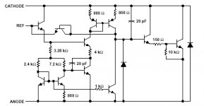
this is the schematic of TL431
adjustable voltage reference
I am truly sorry.
now you can redraw your
"TUBE"-Schematic, analog_sa
You just put in the reality (see picture)
into your circuit,
it will be many more transistors, than tubes!
/halo - is not ashamed to call a transistor circuit
- by its REAL name
Attachments
Hello,
Thanks to all for the response.
Here is also one example of Valve (ECC88/E88CC/6DJ8/6922)
Line Preamplifier that I found, but now in the parallel configuration.
Best regards,
Kristijan Kljucaric
http://web.vip.hr/pcb-design.vip
Thanks to all for the response.
Here is also one example of Valve (ECC88/E88CC/6DJ8/6922)
Line Preamplifier that I found, but now in the parallel configuration.
Best regards,
Kristijan Kljucaric
http://web.vip.hr/pcb-design.vip
Attachments
Another textbook circuit. Nothing to get excited about but one should start from somewhere and this is as good as any other starting point. The circuit will alow you a lot of experimentation and importantly, to make up your mind what you like and what not.
If you do build it as is you'll be able to immediately test single versus parallel triodes and decide which do you prefer. A very contentious issue! Next you can replace the cathode resistors with a 1.2v NiCd battery and see if you like fixed bias. Eventually you may want to try a plate choke/line out transformer/active load but this will likely require a significantly lower plate voltage.
have fun
peter
DANIEL
Hi,
That circuit is an exact copy of Mr.Joe Curcio's "Daniel" preamps' line stage as published in AA issue #2 1985.
Cheers,😉
Hi,
That circuit is an exact copy of Mr.Joe Curcio's "Daniel" preamps' line stage as published in AA issue #2 1985.
Cheers,😉
Kristijan,analog_sa said:Another textbook circuit. Nothing to get excited about but one should start from somewhere and this is as good as any other starting point. The circuit will alow you a lot of experimentation and importantly, to make up your mind what you like and what not.
If you do build it as is you'll be able to immediately test single versus parallel triodes and decide which do you prefer. A very contentious issue! Next you can replace the cathode resistors with a 1.2v NiCd battery and see if you like fixed bias. Eventually you may want to try a plate choke/line out transformer/active load but this will likely require a significantly lower plate voltage.
have fun
peter
Build one version and listen for a while. then rebuild and try the other. 1 hours work for the changeover, and then as Peter said, you can decide for yourself. Don't build it fancy, just use an old scrap of wood as a chassis. I've spent today building a prototype amp on some old scraps of mdf and pine, everything quickly soldered together to see how it works. I'll play with it for a while, and then build it into a good chassis later once I'm happy with it. There will probably be several changes to the circuit if past examples are anything to go by.
Cheers
Cheers
Good ideas by Brett and analog_sa
Some questions:
Where does the current through the stage go when using a battery?
Why the comment on lower voltage when using a trafo or coil?
I have a voltage of around 2.8V (I would have to check on that value since to many changes) at the cathode, this means I'l have to use two batteries in series in order to get the desiered 6 mA through the stage?
Any comments on sound when using batteries?
Can batteries be used when loading with coil or trafos?
I may try the batteries myself.
COILED CHOKES?
Hi,
Sorry...couldn't resist it...oops...another one.
Simply put the choke has much lower voltage drop than an anode R would.
Same as always...ground.
Assuming you measured the potential between cathode and gound...yes.
2 x 1.5V would be fine.
Usually better than resistors.
My advise is to decouple the batteries with some polyprops.
Yes.
Cheers,😉
Hi,
Sorry...couldn't resist it...oops...another one.
Why the comment on lower voltage when using a trafo or coil?
Simply put the choke has much lower voltage drop than an anode R would.
Where does the current through the stage go when using a battery?
Same as always...ground.
I have a voltage of around 2.8V (I would have to check on that value since to many changes) at the cathode, this means I'l have to use two batteries in series in order to get the desiered 6 mA through the stage?
Assuming you measured the potential between cathode and gound...yes.
2 x 1.5V would be fine.
Any comments on sound when using batteries?
Usually better than resistors.
My advise is to decouple the batteries with some polyprops.
Can batteries be used when loading with coil or trafos?
Yes.
Cheers,😉
small remark. specifically use NiCd in the cathode as the cathode current will trickle charge them. other types of batteries may not like it. if you want to use fixed bias in the grid then you may use alcaline batteries or a DC source but then you might need a capacitor at the input. Out of interest some of Counterpoint preamps used this particular configuration in the line stage: parallel ECC88 with 20K plate resistor, -2v grid bias from a regulated PS through 1meg resistor, cathode grounded. Interestingly Counterpoint didn't like cathode resistors much, bypassed or not. In the phono they used the valves in grid-leak mode, with no bias and grid current. Must be the only phono stage i've seen where the cart is cap coupled to the input grid
cheers
peter
cheers
peter
GROUNDED CATHODE.
Hi,
Yes,the cathode was tied to ground and on the cheaper models and a 10 Meg or higher grid leak resistor was used to bias the valves.
On the more expensive models a 1 Meg resistor + regulated bias supply used.
Also the anode supply was valve regulated.
If you used a MC cart + headamp the first coupling cap can often be left out.
IMHO,the grounding of the cathode provides much better bass performance from the preamp.
I always enjoyed the CP products a lot,Michael Elliott knows his tubies.
Cheers,😉
Hi,
Out of interest some of Counterpoint preamps used this particular configuration in the line stage: parallel ECC88 with 20K plate resistor, -2v grid bias from a regulated PS through 1meg resistor, cathode grounded. Interestingly Counterpoint didn't like cathode resistors much, bypassed or not. In the phono they used the valves in grid-leak mode, with no bias and grid current. Must be the only phono stage i've seen where the cart is cap coupled to the input grid
Yes,the cathode was tied to ground and on the cheaper models and a 10 Meg or higher grid leak resistor was used to bias the valves.
On the more expensive models a 1 Meg resistor + regulated bias supply used.
Also the anode supply was valve regulated.
If you used a MC cart + headamp the first coupling cap can often be left out.
IMHO,the grounding of the cathode provides much better bass performance from the preamp.
I always enjoyed the CP products a lot,Michael Elliott knows his tubies.
Cheers,😉
No way Jose
Finished the pre OPT. I managed to put 11,000 turns on the primary and got 180H with a 0.0005" gap, but winding capacity was to large. Only got up to 3K Hz before it started rolling off.
It really worked with 6 mA and thought I had made it,
But no.....
i really want to try this trafo Load/out arrangement. I like this Euridice preamp, since one is able to shoot down the output cap! Plus the possibility to run a balanced line to the amp. With only one active element!
Has someone on this forum have an Euridice so he can comment?
I did two changes to my preamp yesteday.
The first one, replaced the last lytic cap (100uf) that i had on the PSU with an Axon 5,6uf. That really made my day, the sound changed compleatly (better, much much better). The only draw back was that the bass was laking. So I added 25uf with some oil polyprops I had at hand, that restored the balance but still there is some impact at low freq missing.
Is 30uf still low for this position?
The second mod was replacing the Rk with one AA battery, the sound still got better but not as much a difference as changing the lytic.
Now I feel the urge to change the PSU with a 5Y3 rectifier and give away the SS reg, instead using a couple inductors with two poyprop caps, simillar to what T. Loesch did for his Euridice pre.
Would two inductors of say 10/20H and two Solen polyprop caps of 15 and 20 uf do the job?
Actually I'm home brewing the Inductors, started already.
PLAYNG WITH CAPS
Hi,
Sounds like it.
What I suggest you try out is leave the 100 mF electrolytic in place and use the Axon as a decoupling cap.
Put it as close to the anode of the tube as possible.
That would restore the bass and make the mid and treble sound better.
That seems low in value to me.
Keep in mind that the 5Y3GT will only take a couple of mF of input capacitance.
Cheers and happy winding,😉
Hi,
Is 30uf still low for this position?
Sounds like it.
What I suggest you try out is leave the 100 mF electrolytic in place and use the Axon as a decoupling cap.
Put it as close to the anode of the tube as possible.
That would restore the bass and make the mid and treble sound better.
Would two inductors of say 10/20H and two Solen polyprop caps of 15 and 20 uf do the job?
That seems low in value to me.
Keep in mind that the 5Y3GT will only take a couple of mF of input capacitance.
Cheers and happy winding,😉
Re: PLAYNG WITH CAPS
This means a low value cap before the first inductor?
Input capacitance?
Sorry, I'm not an EE so some times i need to hear something more eleborated to understand.
fdegrove said:Hi,
Keep in mind that the 5Y3GT will only take a couple of mF of input capacitance.
This means a low value cap before the first inductor?
Input capacitance?
Sorry, I'm not an EE so some times i need to hear something more eleborated to understand.
PLAYING WITH CAPS
Hi,
Yes.
I was looking at the Euridice and noticed they used a 47 mF cap as the input cap in the filter.
Also some other remark: did you notice the 15K/50W resistor in the PSU?
They are burning a lot of voltage that way...but before I make further comments I'd rather take a close look at the circuit.
Cheers,😉
Hi,
This means a low value cap before the first inductor?
Yes.
I was looking at the Euridice and noticed they used a 47 mF cap as the input cap in the filter.
Also some other remark: did you notice the 15K/50W resistor in the PSU?
They are burning a lot of voltage that way...but before I make further comments I'd rather take a close look at the circuit.
Cheers,😉
- Status
- Not open for further replies.
- Home
- Amplifiers
- Tubes / Valves
- basic e88cc line stage ?