Baldin, you should take a look at my signature in order to get LTSpice's FFT function to perform its best. For convenience, here is a block of text I sent someone else about this subject.
For everyone interested in de-corrupting the noise floor:
I've attached the BAKSA schematic with a set of simulation parameters which should allow for a very low noise floor. Keep all the files in the same folder. Please take a look at the simulation commands and familiarize yourself with how they perform. When performing an FFT, select the same number of points as the FFT parameter on the schematic. There is also an option "quadratic interpolate uncompressed data" which corrupts the noise floor that you can uncheck.
There is also a loudspeaker model included in the schematic to help make it realistic... Unfortunately it's time constants degrade the noise floor. I'm not sure how well this will work, the inductors may be broken (even if so, the rest of the schematic should work fine). We shall see...
- keantoken
This should help you get consistent FFT results.In transient analysis, noise is not simulated. The noise floor of the FFT is usually a result of digital smoothing which happens when the FFT doesn't use the same number of samples as the input data. The downward slant of the noise floor is the result of capacitor drift because of inaccurate operating point solution; the circuit is still settling during the analysis because the simulator doesn't have the exact operating point solved.
So it is in fact possible to get a -240db noise floor, and I see a low simulation noise floor as necessary because a high one can be misleading. Here are some things which will allow you to lower the noise floor:
1: Eliminate DC drift from the signal path. Measure voltages of signal and offset capacitors, and replace them with voltage sources of the same value. Power supply caps will have little affect as long as your amp has decent PSRR.
2: When you right-click and open the FFT menu, select the same number of samples used for the simulation (num_fft_pts in the pictures below). This eliminates the need for digital smoothing, which corrupts delicate data.
3: Run one or two pre-cycles to warm up, before the testing period. Even if the operating point has been found perfectly, the abruptly starting sine input will cause DC drift of its own, after sending a surge through the circuit.
For everyone interested in de-corrupting the noise floor:
I've attached the BAKSA schematic with a set of simulation parameters which should allow for a very low noise floor. Keep all the files in the same folder. Please take a look at the simulation commands and familiarize yourself with how they perform. When performing an FFT, select the same number of points as the FFT parameter on the schematic. There is also an option "quadratic interpolate uncompressed data" which corrupts the noise floor that you can uncheck.
There is also a loudspeaker model included in the schematic to help make it realistic... Unfortunately it's time constants degrade the noise floor. I'm not sure how well this will work, the inductors may be broken (even if so, the rest of the schematic should work fine). We shall see...
- keantoken
Attachments
Hi keantoken
Thanks a lot, you are a genius ..... thanks for sharing, and the example is just the way to explain things. Thanks.
....
got me searching a bit (think I have not spent enough time on the SS forum ... there is a lot of really great stuff here 😎 .... of course) and found this TGM amp thread ..... maybe it gives the answer to the challenge
http://www.diyaudio.com/forums/solid-state/168503-tgm-amp-goes-tubey.html
Ok after reading some more ... I see it is probably something else than what is used in AKSA ... sorry 🙁 ... but the thread is quite interesting anyway 😉
why appologise?
You responded to Aksa's challenge.
Good on you.
Nobody else has posted their attempt.
You responded to Aksa's challenge.
Good on you.
Nobody else has posted their attempt.
True enough, Baldin. Gudonya, you had a go at it!
The circuit is so simple, however, that the permuations remaining are limited.
I have had serious dialogue with Keantoken. He is a 16 year old genius, to be precise. I too believe he is absolutely brilliant, shames me with my puling Masters degree in IT...... a shining intellect, I hope he gets a very good education, he deserves it.
However, have another stab, you might get there, you too Andrew!
Hugh
Even if I am a genius, the secret mechanism still eludes me.
The difficult thing is that the only description for this mechanism is that it's hidden and subtle... So I would find it by looking for something I don't know already? But if, by chance, I had seen it before and paid it no attention, then I would yet be looking in the wrong place...
One of the reasons I included the loudspeaker model in the simulation was to see how reactive loading affected behavior... With resistive loads we always assume crossover happens at 0V but with reactive loads this is not true. I haven't studied a lot on how this affects the spectrum.
I could explain my understanding of the circuit from start to finish, if someone's interested?
- keantoken
by all means .. .. especially if it could show the effect of back emf with VAS bootstrap vs. current source.
I have played some more with LTSpice, and I only finde minute differences (5. decimal in distortion!!) between CS and bootstrap!
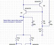
Have though found another way of introducing primarily 2. ord harmonics:
Place a small cap at the current source output to GND for the LTP.
I have played some more with LTSpice, and I only finde minute differences (5. decimal in distortion!!) between CS and bootstrap!
Have though found another way of introducing primarily 2. ord harmonics:
Place a small cap at the current source output to GND for the LTP.
Attachments
Last edited:
Hmm, you are introducing asymmetrical charge/discharge, which promotes H2, BUT, you are also using 1st order shunt compensation, which pulls back OLG at high frequency. This means you can ease off on the conventional CB lag compensation, which improves sonics somewhat.
Why not try it....
Hugh
Why not try it....
Hugh
The cap will increase H2 at high frequencies but not at lower ones. To have the same effect across the spectrum you could replace the CCS with a resistor, or replace the cap with a resistor. I agree with Hugh.
I'm afraid I will have to sleep again. I've spent a lot of time deliberating on exactly what was the best way to explain a circuit... My first attempt was to take each component individually and explain it's function, but this does not help explain the big picture. I started on a rough draft trying to find the best angle to begin the explanation with... I think I'm getting there, let's just say, if I ever finish, it will be comprehensive. If not, I'll be sure to post something useful, even if less ambitious.
- keantoken
Last edited:
I'm afraid I will have to sleep again. I've spent a lot of time deliberating on exactly what was the best way to explain a circuit... My first attempt was to take each component individually and explain it's function, but this does not help explain the big picture. I started on a rough draft trying to find the best angle to begin the explanation with... I think I'm getting there, let's just say, if I ever finish, it will be comprehensive. If not, I'll be sure to post something useful, even if less ambitious.
Hi keantoken,
I found this to be a well written, detailed discription of an amplifier. It may help.
http://home.alphalink.com.au/~cambie/ETI480/ETI480.zip
regards
Greg
Aha, Greg,
Years ago, when that was written, Paul and I were very good friends. A pity, we don't see each other these days, he's on one side of Melbourne, I'm on another, and people move on. Lovely guy, and very clever,
Hugh
Years ago, when that was written, Paul and I were very good friends. A pity, we don't see each other these days, he's on one side of Melbourne, I'm on another, and people move on. Lovely guy, and very clever,
Hugh
Well, that is pretty comprehensive compared to my vision... Let me humble myself.
I don't want to get into what rails are necessary for what wattage, what output devices to use, etc. I intend to discuss the amp from a signal standpoint, how the mechanisms work and how they interact with the signal passing through.
- keantoken
I don't want to get into what rails are necessary for what wattage, what output devices to use, etc. I intend to discuss the amp from a signal standpoint, how the mechanisms work and how they interact with the signal passing through.
- keantoken
That sounds perfect to me Keantoken!! 🙂 It should be a good excercise for you as well, as often when working out how to explain something to someone else it results in questioning ones own thoughts and a deeper understanding than you started with!
Tony.
Tony.
yes, Bob Cordel said something similar.That sounds perfect to me Keantoken!! 🙂 It should be a good excercise for you as well, as often when working out how to explain something to someone else it results in questioning ones own thoughts and a deeper understanding than you started with!
Tony.
I find that when I have a problem and try to explain it to another. As I form understandable and logical sentences explaining the problem, I can see the answer that while alone I could not see.
I remember teaching a year11 class about using an opamp.
I had drawn on the whiteboard a diagram with pin 4 & 7 swapped.
I was looking over the shoulder of a pupil setting out the opamp and various connections when I realised that he was doing it wrong. That +ve supply does not go there!!!
OOPs, he had copied exactly what I had shown on the white board.
Everybody STOP. I have made a mistake.
It was the process of thinking it through in the presence of the pupil that brought the realisation to me.
This type of interaction works for me, regularly, in industry, in the design office, in the classroom, with another department when otherwise working alone.
It is a powerful technique for clearing one's thoughts.
Last edited:
Yes I had this experience when I was at Uni Andrew 🙂 I had a friend who was struggling with physics and I was explaining stuff to him (a lot of the time having to really think about it to do so) and in the end he passed and I got a high distinction! Similarly I remember doing a uni class where we were doing 68000 assembler on Mac's and helping others solve their problems really improved my knowledge.
It works the other way around as well, like you mentioned. When I was at school and I was struggling with Maths, my parents would ask me to explain to them what it was that I was supposed to be working out, in the process of explaining it to them I would realise what it was I was doing wrong and solve the problem. I do believe that often the most powerful source of learning is actually teaching someone else.
Tony.
Other people serve as a feedback mechanism - they make it easier to be correct! That is, if you can let go of some self-importance. And we hope, as the end result, as we refine our process, that one day we will be able to function on our own - without global NFB! Ah... I feel like such a geek now. 😀
Winter, you are exactly right. I've formulated a way to begin my explanation. I wouldn't have thought to look at things this way if I wasn't trying to explain it clearly, but the results are interesting and I've discovered a clearer way to test certain aspects of the circuit.
- keantoken
Winter, you are exactly right. I've formulated a way to begin my explanation. I wouldn't have thought to look at things this way if I wasn't trying to explain it clearly, but the results are interesting and I've discovered a clearer way to test certain aspects of the circuit.
- keantoken
- Home
- Amplifiers
- Solid State
- Based on Hugh Dean's AKSA 55