I had experimented on my commercial speaker. It is a 3-way with a tweeter, a dome midrange and a woofer. The original crossover network for mid used components that are nearly symmetric: 11 uF + 0.6 mH for low pass and 11 uF + 1 mH for high pass. The calculation suggested there was a bandpass filter with 1.5 kHz HP and 1.9 kHz LP. I tried to convert it from a bandpass to a bandstop filter by adding a 10 uF capacitor parallel to the 11 uF of low pass section, thus, total capacitance is 21 uF. Now, the LP section became 1.4 kHz cut-off frequency from calculation. Expecting that this would created a bandstop filter by theory, the result wasn’t at that though. I could hear the midrange sound from the midrange. Could anyone please explain me why? Also, another question, is the original crossover weird design? Says is it too narrow bandwidth for bandpass design? I’ve heard that the closeness of LP and HP section should not be exceeded some number of octaves, not sure 1 or 2, could anyone please clarify me? Thank you
Reducing that separation is going to lead to more interaction between the sections. This isn't a bad thing, unless there is no way of measuring or predicting the result, in which case the separation is playing it safe.
Some designs only use the mid to fill a hole. For this reason I'd keep an open mind at first.
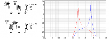
The order of components makes a difference. Maybe a sim could point things in the right direction (this sim doesn't figure in the specific impedance, response or overall purpose, and guesses at inductor resistance). Which circuit variation do you have?
Also note that the filter responses go above 0dB, connected with the interaction.
Some designs only use the mid to fill a hole. For this reason I'd keep an open mind at first.
The order of components makes a difference. Maybe a sim could point things in the right direction (this sim doesn't figure in the specific impedance, response or overall purpose, and guesses at inductor resistance). Which circuit variation do you have?
Also note that the filter responses go above 0dB, connected with the interaction.
Attachments
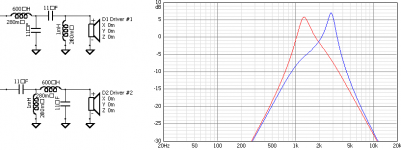
On second thoughts it occured to me what you were trying to do - invert the effect by overlapping (reversing the positions of) the high and low pass filters.
This is not what will happen. Their interaction represents a resonance with a bandpass effect on the speaker due to the topology of the circuit. Changing the values affects the resonance.
If you look closely you can still see there is an upper and lower knee.. they are just in disarray (at least in this presumptuous sim)
In this sim I overlapped them by halving the low pass frequency and doubling the highpass frequency. Also note that other Q values could be arranged around the same frequencies.
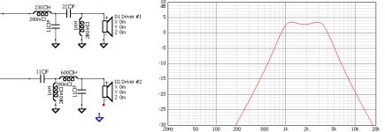
Notice that the primary band is still centred around 2kHz.
This is not what will happen. Their interaction represents a resonance with a bandpass effect on the speaker due to the topology of the circuit. Changing the values affects the resonance.
If you look closely you can still see there is an upper and lower knee.. they are just in disarray (at least in this presumptuous sim)
In this sim I overlapped them by halving the low pass frequency and doubling the highpass frequency. Also note that other Q values could be arranged around the same frequencies.
Notice that the primary band is still centred around 2kHz.