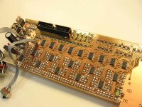
Just finished an Opamp based pre, with Shunt relay volume control, driven by discrete ADC.
Basically, it's just another IC preamplifier.
The only thing little out of the oridinary is in the volume control circuit.
I wanted to use VR pot instead of encoder, because the knob indicate itself,
no need for any other display unit, also without needing to use MCU.
In my first prototype, I used ADC0804 to encode the DC voltage from Log volume pot.
VR pot -> ADC chip (parallel output) -> shunt relay
I thought 8-bit ADC can resolve the smallest pot movement, but I was wrong.
When turning the pot slowly, VR voltage enters imtermediate level between steps, and the Relays oscillate like crazy.
There is no way to add hysteresis to the ADC chip, so I have to build my own ADC instead.
VR pot -> ladder comparator (0111) -> XOR logic (0100) -> diode mapping -> shunt relay
It turn out to be a clumsy low tech configuration, with lots of diode and logic chip, but no MCU.
Attachments
Simplified schematic for the audio main board.
Red path is for RCA input:
Blue path is for XLR input:
Red path is for RCA input:
Blue path is for XLR input:
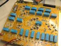
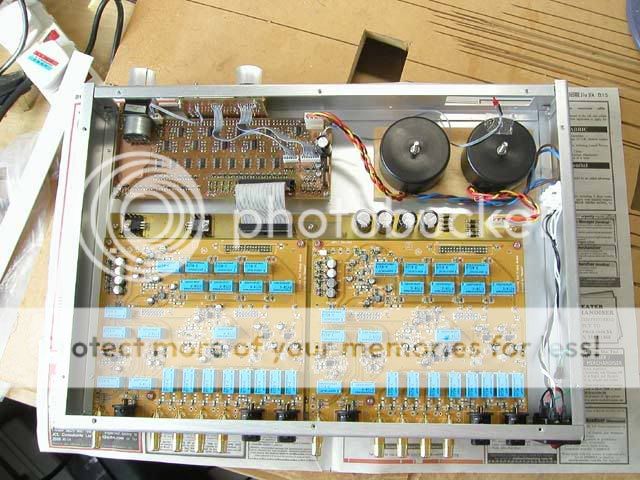
Stackup of the PCBs:
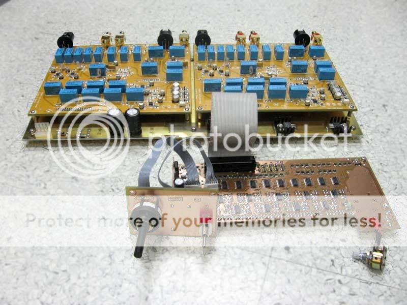
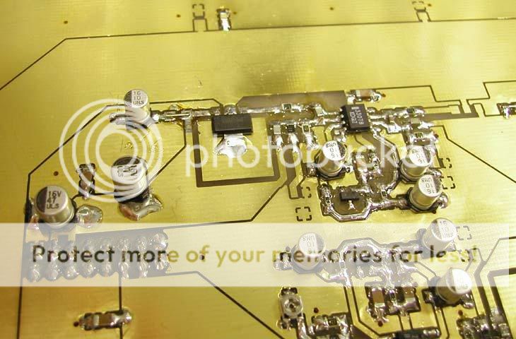
Golden board under the audio main board is the power supply. Regulator circuit components are soldered at the bottom side.
I was too cheap and made the supply board without soldermask, it looks a bit messy.
Golden board under the audio main board is the power supply. Regulator circuit components are soldered at the bottom side.
I was too cheap and made the supply board without soldermask, it looks a bit messy.
I used AD797 as the output buffer (after shunt relay volume). The input buffer is LME49710.
Putting everything inside the box.
Putting everything inside the box.
Hi Banana,
Great work! Is it for production or just your DIY project. On your initial ADC work, you might need to add a Gray code encoder so you have dictinct state while you rotate the VR setting, thus remove the oscillation between relays. Now I guess you are using "one-hot" state machine on your discrete approach. What is in your diode mapping scheme?
Can we do it in 8 relays to get 256 different states, like more than one of the 8 shut resistors engaged in parallel to get you lower volume? I would like to know more about your project and keep in touch.
Regards,
Adam
Hi Ampliton,
It's my home brew DIY project only 😉
I didn't use gaycode encoder because it must be used with MCU + separate level display. Also, with VR+ADC, remote control can be added easily. And the real reason is that I'm bad in MCU programming, and I'm trying to avoid it.
There are 8 shunt relays and 256 levels, but only 40 control steps. The diode mapping is to route each logic output to the desire relays, step by step.
Yes, more attenuation can be achieved by adding shunt relay. Since I finished the audio main board layout before I discover the oscillation problem, I keep using eight.
Attachments
Some measurement to show.
Residue noise (Gain = 0dB, 20KHz filter)
OPA227>VR>LME49710 = 3.5uVrms
LME49710>VR>AD797 = 2.7uVrms
THD figure is virtually the same for both Opamp combination.
In fact, 2nd harmonic -120dBc, 3rd harmonic -110dB are the equipment limit.
I guess it'll be the same case for many modern Opamps, harmonic product were below the measurement limit of AP...
Hi Banana,
Thanks for the update, and I am impressed that you own the Audio Precision. Is it an AP-1 or AP-2? How does it sound compared to commercial product? Did you design and etch your PCB? Thanks for sharing.
Regards,
Adam
Thanks for the update, and I am impressed that you own the Audio Precision. Is it an AP-1 or AP-2? How does it sound compared to commercial product? Did you design and etch your PCB? Thanks for sharing.
Regards,
Adam
Some hysteresis trick with the ADC reference would have solved the problem.
Just a quick thought, how, I don't know.
Gajanan Phadte
Just a quick thought, how, I don't know.
Gajanan Phadte
Hi Ampliton,
That's AP2 dual domain, but I didn't own it
I designed all PCBs and etched the discrete ADC board by myself. The audio main board (4-layer) and power supply board (double side) were made by sample house.
I don't have other commercial preamp to compare with right now. But I'll lend this preamp to my friends and hear their comment soon.
Hello Banana,
I like your idea !
I've started to think to a same kind of project but I've never start to do something. Is it enough if I ask you to get the schematic ?
Thanks

I like your idea !
I've started to think to a same kind of project but I've never start to do something. Is it enough if I ask you to get the schematic ?
Thanks
Hi Gmphadte,gmphadte said:Some hysteresis trick with the ADC reference would have solved the problem.
There is no access to the comparator front end inside the ADC chip, hysteresis can only be applied after the DC voltage is encoded. Some memory buffer plus MCU programming should do, but I've turned to the hardaway before figure out how...
When it is a hysteresis problem, invariably the VU led meter ICs come to my mind as a simple, easy-to-lay solution. However 50 steps will pose some problems. Moreover the encoding will need some more ICs.
So much to get some hysteresis...anyhow, it is another solution
Gajanan Phadte
So much to get some hysteresis...anyhow, it is another solution
Gajanan Phadte
A little problem measuring intermodulation with AP2.
Again, every opamp combination measured the same. I tried direct connect feed, and confirmed it's equipment limitation.
Input signal 19KHz+20KHz, 3.6Vrms, AP2 analog out to analog in (XLR->XLR)
There's a strange 500Hz sideband I didn't expected, FFT plot below.
Then I use the SPDIF output from AP2, connected to my AD1853 DAC as the analog generator.
http://www.diyaudio.com/forums/showthread.php?s=&threadid=80253&perpage=25&pagenumber=1
Now the sideband is gone, noise floor is lowered, and difference between OPA227 and AD797 is revealed.
Casing finished.
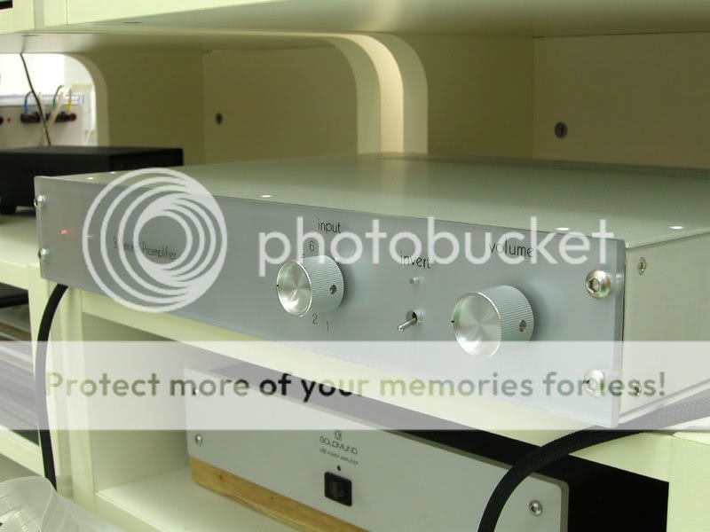
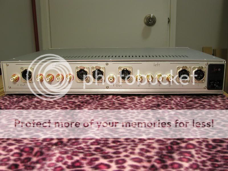
I used the detachable type Neutirk XLR socket, which is quite expensive. Also there are very few choices of PCB mount RCA socket available. Sadly I can't afford those luxurious brand like WBT and Cardas.
I used the detachable type Neutirk XLR socket, which is quite expensive. Also there are very few choices of PCB mount RCA socket available. Sadly I can't afford those luxurious brand like WBT and Cardas.
- Status
- Not open for further replies.
- Home
- Amplifiers
- Chip Amps
- Banana's Pre - inelegant way to contrl vol