Page 1 of the discrete ADC schematic.
Total 10 quad comparators. In order to gain some precious PCB real estate, I use the more expensive push-pull comparator (instead of good old LM339). 40 pullup resistors are save.
LVL01 is the maximum attenuation. Below LVL01 is mute state, and opamp output relay will open.
LVL37 is 0dB attenuation, all 8 shunt relays are open.
LVL38~39 are the active gain state, audio signals are rounted to the variable gain opamp, without passing through the shunt relay attenuator. The comparator is connected as non-inverting for these 2 levels.
Attachments
Page 2, the XNOR chain.
This logic stage is to convert the cummulative output from comparator into decimal (01111 -> 01000).
Diode delay is added to some levels, to create anti-pop "make before break" for the relays. It's only required when relay state carries to the next digit (011 -> 100).
This logic stage is to convert the cummulative output from comparator into decimal (01111 -> 01000).
Diode delay is added to some levels, to create anti-pop "make before break" for the relays. It's only required when relay state carries to the next digit (011 -> 100).
Attachments
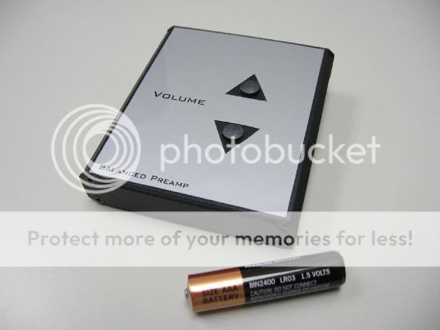
Now another clumsy logic circuit, a remote control for my preamp.
Elementary FSK, 310Hz for volume down, 435Hz for volume up.
To avoid interference from other remote, IR carrier is 16.384KHz, much lower than normal 38K.
Receiver side is just bandpass pass filter, and a BJT H-bridge to drive the motorised volume pot.
Elementary FSK, 310Hz for volume down, 435Hz for volume up.
To avoid interference from other remote, IR carrier is 16.384KHz, much lower than normal 38K.
Receiver side is just bandpass pass filter, and a BJT H-bridge to drive the motorised volume pot.

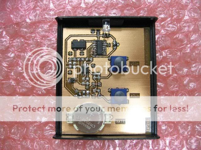
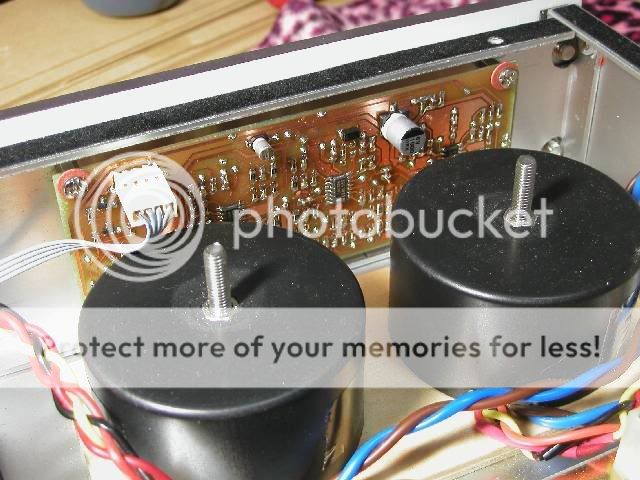
A photo of the IR receiver board, mounted behind the front panel.
An externally hosted image should be here but it was not working when we last tested it.
Thanks Jopie.
I was using passive preamp (24 steps grayhill switch) for years, and in fact I couldn't notice substantial difference after switching to the new preamp. The LME49710 is quite neutral and quiet.
The user control is better, there are finer steps in the low volume range, volume knob is much smoother than the stiff old grayhill, and now I have a remote.
Page 1 of the IR receiver schematic.
IR photodiode -> I/V converter -> 16.384KHz bandpass filter -> Diode peak detect ->>
I cannot set the 16K bandpass gain too high, otherwise it'll be interfered by other 38K remote unit in close distance, despite the wide difference in carrier frequency.
IR photodiode -> I/V converter -> 16.384KHz bandpass filter -> Diode peak detect ->>
I cannot set the 16K bandpass gain too high, otherwise it'll be interfered by other 38K remote unit in close distance, despite the wide difference in carrier frequency.
Attachments
- Status
- Not open for further replies.
- Home
- Amplifiers
- Chip Amps
- Banana's Pre - inelegant way to contrl vol