Good afternoon!
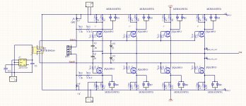
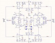
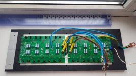
I am building a balanced version of the F5 turbo. The input circuitry and the power driver circuitry are shown in the diagrams. Now I'm doing the tuning.
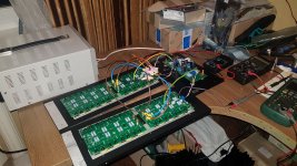
The amplifier is powered from a laboratory source + -30V. In the positive arm of the amplifier, 8 pairs of transistors and, accordingly, in the other in the same way, all are selected up to 0.01V.
I set the quiescent current to about 50mV on a 0.5Ω resistor. In this case, it is possible to achieve an offset at the amplifier output of about 0 mV. With an increase in quiescent current, setting zero offset remains possible.
That is, the constant current mode amplifier is stable.
If I apply a sinusoidal signal to the input "+" and the input "-" with a phase shift of 180 degrees with a frequency of 1 kHz, the amplitude is 1V - at the output (without load) everything is fine. The current consumption of the amplifier is about 1A.
The problem disappears with increasing frequency. The amplifier starts to draw a lot of current. 5kHz - 1.6A, 10kHz-2A, 20kHz-2.6A. If you increase the input signal level, the current will also increase.
Please tell me what I'm doing wrong or somewhere wrong.
Thank you in advance.
I am building a balanced version of the F5 turbo. The input circuitry and the power driver circuitry are shown in the diagrams. Now I'm doing the tuning.
The amplifier is powered from a laboratory source + -30V. In the positive arm of the amplifier, 8 pairs of transistors and, accordingly, in the other in the same way, all are selected up to 0.01V.
I set the quiescent current to about 50mV on a 0.5Ω resistor. In this case, it is possible to achieve an offset at the amplifier output of about 0 mV. With an increase in quiescent current, setting zero offset remains possible.
That is, the constant current mode amplifier is stable.
If I apply a sinusoidal signal to the input "+" and the input "-" with a phase shift of 180 degrees with a frequency of 1 kHz, the amplitude is 1V - at the output (without load) everything is fine. The current consumption of the amplifier is about 1A.
The problem disappears with increasing frequency. The amplifier starts to draw a lot of current. 5kHz - 1.6A, 10kHz-2A, 20kHz-2.6A. If you increase the input signal level, the current will also increase.
Please tell me what I'm doing wrong or somewhere wrong.
Thank you in advance.
Attachments
put lag caps across feedback resistors
there is an info in F5T thread which values Papa advised , but you can shoot for 120-150K corner frequency without too much guesing
there is an info in F5T thread which values Papa advised , but you can shoot for 120-150K corner frequency without too much guesing
Thanks for the answer!put lag caps across feedback resistors
there is an info in F5T thread which values Papa advised , but you can shoot for 120-150K corner frequency without too much guesing
Of course, I tried to install capacitors in parallel with 110 Ohm resistors with a nominal value of 1N, but it did not work for me. 1n is that value that was recommended in the branch about F5T, maybe another value is needed? Do I need to install a capacitor parallel to each 110 ohm resistor?
__________________
__________________
__________________
Added capacitors in parallel with feedback resistors (21n capacity). Current consumption at 20 kHz has decreased. Below is an oscillogram of a 1 kHz rectangular signal. The form is not ideal. The power supply makes a sound like a whistle 🙂 What to do next? Please help with advice.
Attachments
can you try that with nice linear power supply ?
one can try messing with amps , using lab supply only when sure and confirmed that Lab Supply is real and proper Lab Supply , not whinging apparatus
so ?
one can try messing with amps , using lab supply only when sure and confirmed that Lab Supply is real and proper Lab Supply , not whinging apparatus
so ?
I agree. I'll try to assemble an amplifier with a real power supply. Transformer 2.5kVA, + -44V. I will show progress. 🙂
one thing , for now - why harassing tiny JFets with 30V at drains , when you have cascodes ?
bring that to 12V or so , to keep them warm and happy in same time
bring that to 12V or so , to keep them warm and happy in same time
I've noticed that ZM thinks little jfets are to be treated nicely, not to be flogged like lowly dumb mosfets. But then drive.... well, parallel up when needed. Makes sense 🙂
current through them (JFets) is what giving you drive(ability) , from multiple reasons (slight increase in xconductance but mostly due to decreased drain resistyance , thus Rout of stage) , while excessive voltage is just heating them
Thank. Of course I will write about the sound and show the whole project. Moreover, I can compare with different amplifiers.nice project RsD, tell us how it sounds🙂
OK.🙂 I changed the cascode divider. Now about 14V on the drain.one thing , for now - why harassing tiny JFets with 30V at drains , when you have cascodes ?
bring that to 12V or so , to keep them warm and happy in same time
I need a few days to assemble the whole structure with a real power supply.
Hello! 🙂
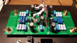
I continued to build and launch the balanced F5T. In principle, the behavior of the amplifier is the same as when turned on with a laboratory power supply. The quiescent current is established, the offset at the output is about 0mV. When I gave a musical signal the sound appeared. Sound without noticeable distortion, even very interesting. Now about the incomprehensible: at start, the amplifier consumption after 1 hour of heating is about 250W without an input signal and the power consumption is stable. When a music signal is connected, the amplifier starts to warm up and the power rises to 800W 😕, I’m afraid to continue heating.
The first thing that comes to mind is self-oscillation. I tried to install capacitors C1, C2 (designations in the current circuit) 2p2, 22p, 47p, 220p, 1n, 10n, the picture does not change. Attempts to install capacitors parallel to the resistors R8-R13 (and on all shoulders) also does not change anything. I'm out of ideas. Maybe this is the normal mode of operation of the amplifier. Can an amplifier work with so many output transistors and at low power?
Attachments

hi RSD, I recall ZM saying to put caps across feedback resistors:
https://www.diyaudio.com/forums/pass-labs/207103-f5-turbo-builders-thread-98.html#post5219724
https://www.diyaudio.com/forums/pass-labs/207103-f5-turbo-builders-thread-98.html#post5219724
hi Luke!hi RSD, I recall ZM saying to put caps across feedback resistors:
https://www.diyaudio.com/forums/pass-labs/207103-f5-turbo-builders-thread-98.html#post5219724
May you tell me how to calculate the value of the capacitor in the feedback? Or can you tell me which approximate value of the capacitor to install? And maybe I didn’t fully understand where to install these capacitors, may you indicate on the circuit Or can anyone? Help 🙂
Thanks
hi RsD, it says in the post 3n9-4n7. Good luck, and nice pic, I'm sure you will get this amp singing🙂
I had time to deal with my amplifier. Another attempt to adjust. Here's what I got.
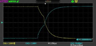
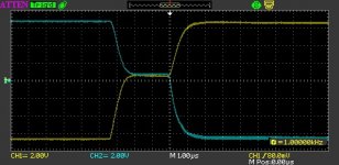
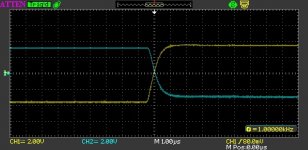
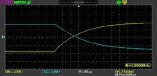
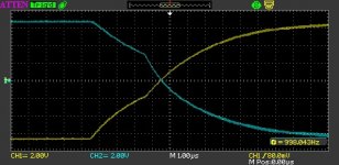
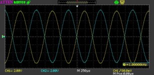
I connected to the input of the amplifier Meander 1kHz, 1.5V. If for example only output rectangles are positive or negative, I would say that they are in perfect shape, but with different levels.
If you give a balanced signal, then the output is horrible! I attach the screenshots: without correction and with correction with a capacitor from 1n to 21n. With an increase in frequency to 20 kHz, the current consumed by the amplifier increases by 2A from the base.
The conclusion suggests itself that with balanced switching on, it is necessary to remove the self-oscillation of the amplifier in some other way.
Attachments
- Home
- Amplifiers
- Pass Labs
- Balanced version of the F5 Turbo