Hello,
I´m planning to modify my preamp so it can produce a balanced output signal.
Since it is opamp based I think this can be done quite simple by using a second (inverting) output opamp.
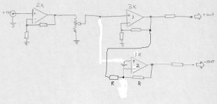
Is it possible to feed two opamps with the same input signal without using resistors to separate the inputs? If not wich value would be appropriate? The opamps are OPA627, the first (input) has a gain of 2, the second (output) a gain of 3. The volume control is between the two opamps.
(see drawing if I can upload it)😕
william
I´m planning to modify my preamp so it can produce a balanced output signal.
Since it is opamp based I think this can be done quite simple by using a second (inverting) output opamp.
Is it possible to feed two opamps with the same input signal without using resistors to separate the inputs? If not wich value would be appropriate? The opamps are OPA627, the first (input) has a gain of 2, the second (output) a gain of 3. The volume control is between the two opamps.
(see drawing if I can upload it)😕
william
Attachments

wuffwaff
Your second (inverting) op-amp will not work with the arrangement you have shown (the feedback connections are wrong).
I suggest that you take a feed from the output of your x3 op-amp and connect it to the inverting input of the additional op-amp via a 100kohm resistor. Connect a 100kohm resistor from the output of this op-amp to the inverting input and another 100kohm from the non-inverting input to ground. This will cause the additional op-amp to work as a unity gain inverting buffer and will give you your balanced output.
email me if this is not clear and you need a schematic.
Geoff
Hello wuffwaff,
this circuit will not work, because the second opamp will oscillate. The feedback has to go to the inverting input, and one resistor from there to the volume control instead of the ground (standard inverting circuit); the noninverting input shall be grounded. The gain would not be A=1+R1/R2 but A=R1/R2 where R2 is the resistor to ground resp. to the volume control, so the resistor values of the feedback will be different despite of the same gain.
I´ll try to post a pic, not sure if it will work...
Ciao
AndyM
You already have the 3 x gain in the first opamp.. You only need to invert the signal.
I would decrease the bandwith a bit on the OPA627 so it would not have trouble driving 1 nF - 10nF loads ..
check this pdf file :
http://www.analog.com/productSelection/pdf/AD8610_0.pdf
and look at the last pages .. it does not look good at all!!
Sonny
I would decrease the bandwith a bit on the OPA627 so it would not have trouble driving 1 nF - 10nF loads ..
check this pdf file :
http://www.analog.com/productSelection/pdf/AD8610_0.pdf
and look at the last pages .. it does not look good at all!!
Sonny
It is okay claus, but you have to be carefull that the inverted out is not loading you volumecontrol to much. .. When you use a 10K potmeter the feedback resistor have to be in the area of 100k not to load the potmeter.
Large resistor will increase noise and distiortion on the opa627 and a lot of other opamp's.
sonny
Large resistor will increase noise and distiortion on the opa627 and a lot of other opamp's.
sonny
Thank you all,
this is what happens when drawing without thinking....
Here´s a new one. I would really like to have only two opamps in the signal path so I would like an inverting amp with a gain of -3.
I´ve added the actual resistor values of the existing circuit. The volume control is an elma stepped attenuator of 20k.
william
Attachments
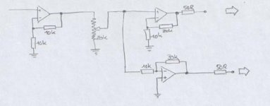
Now your volume pot has a 20K ohm load, so the attenuation per rotation curve is not what you'd expect. Stick a buffer after the pot (a dual JFET source follower with current sink would be nice) OR choose your switched attenuator resistor values with the 20K ohm factored in to give you the desired attenuation. The JFET buffer would drive both opamp inputs.
Now, you know the frequency response, distortion, noise gain, transient response, etc for both gain paths is NOT the same, don't you? 🙂 Have fun adding compensating caps, trimming, etc. for best match or buy a converter from AD or Burr Brown.
Good Luck!
Michael
Now, you know the frequency response, distortion, noise gain, transient response, etc for both gain paths is NOT the same, don't you? 🙂 Have fun adding compensating caps, trimming, etc. for best match or buy a converter from AD or Burr Brown.
Good Luck!
Michael
wuffwaff.... you'd be best to use the circuit that sonnya has posted as it will be the most reliable and cause the least number of problems. It will also meet your criteria of 2 opamps in each signal path.
Hi William
May i suggest DRV134/DRV135 from BB/TI (same company!) They are enhanced dropin replacement for SSM2142 from AD.
DRV134 and DRV135 are identical devices in different housing. DRV135 is in a SO8 house where it can't dissipate as much heat as the DRV134 ... Long cables or a load smaller than 600Ohm => DRV134
😉
Sonny
Hi William,
Types i do not know. I think i stick with the types Sonny suggested.
Most important is that the opamps inside are matched due to the fact that they are made on 1 piece of silicon. Perfect temperature and etc.... matching.
grtz
Simon
Types i do not know. I think i stick with the types Sonny suggested.
Most important is that the opamps inside are matched due to the fact that they are made on 1 piece of silicon. Perfect temperature and etc.... matching.
grtz
Simon
- Status
- Not open for further replies.
- Home
- Amplifiers
- Solid State
- balanced output