I'm simulating the balanced line stage using the demo version of Multisim 2001 and i'm finding behaviors i don't understand:
1) If I enter with the signal source common in the negative input I obtain a perfectly balanced output but with a poor distortion performance (0.26% THD @ 10KHz)
2) If I ground both the signal source common and the negative input of the circuit I obtain a little unbalanced output (about 1Vpp difference on a 11Vpp output) but with a great improvement in the distortion figure (0.008% THD @ 10KHz)
The theory tells that the correct configuration for use with unbalanced input is that of 2, but this seems to be not applicable if i want to drive an amplifier with balanced input or to bridge a conventional stereo amp.
So, what to do ?
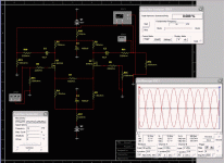
I attached the image of point 2 to explain the low distortion but the unbalanced output
Thank You
1) If I enter with the signal source common in the negative input I obtain a perfectly balanced output but with a poor distortion performance (0.26% THD @ 10KHz)
2) If I ground both the signal source common and the negative input of the circuit I obtain a little unbalanced output (about 1Vpp difference on a 11Vpp output) but with a great improvement in the distortion figure (0.008% THD @ 10KHz)
The theory tells that the correct configuration for use with unbalanced input is that of 2, but this seems to be not applicable if i want to drive an amplifier with balanced input or to bridge a conventional stereo amp.
So, what to do ?
I attached the image of point 2 to explain the low distortion but the unbalanced output
Thank You
Attachments
Simulation
I find that measurements referenced to ground are a real good idea for Spice simulation. The circuit you are analyzing is really optimized for a differential input, and will have compromised performance when driven single ended. Connection to the negative suppy with a current source will help the single ended performance.
"1) If I enter with the signal source common in the negative input I obtain a perfectly balanced output but with a poor distortion performance (0.26% THD @ 10KHz)"
This is driving the input differentially, but there is no ground reference for the input. I have been burned like this before. Drive one input with the method in part 2 and the other input with a voltage controlled voltage source with a gain of 1 and the phase reversed and you should get more acurate results.
Doesn't anybody build stuff anymore? Simulation for audio circuits is needless overkill. We are not building Mars landers.
The only accurate distortion measurements come AFTER you build it.
Jocko
The only accurate distortion measurements come AFTER you build it.
Jocko
The views expressed by the following do not reflect
Simulation is useful when you know its constraints and I like it for lots of things. I don't trust it for distortion measurements. How about you fellow Spicers tell Jocko how you feel. You can't hurt his feelings, I swear!
H.H.
Spice is nice.
Simulation is useful when you know its constraints and I like it for lots of things. I don't trust it for distortion measurements. How about you fellow Spicers tell Jocko how you feel. You can't hurt his feelings, I swear!
H.H.
Spice is nice.
I think simulation is especially valuable for us novices, as it is faster and cheaper to make mistakes in simulation than in real life.
It took me three days of work on the simulator (with help from the forum) to get my 5687 LTP to the point where I was ready to build it. Had I been prototyping and forced to make each voltage, current, and distortion measurement by hand, I probably would have given up in disgust...not to mention the time to construct all of the iterations. It's kind of hard to breadboard tube circuits!
No, the distortion measurements aren't accurate, but when I go from 1% to 0.0001% in a circuit, I have a good idea what is probably working and what isn't.
Jam
Please feel free to tell Jam what you think about him also, and show even less restraint.
H.H.
P.S. I already know what everyone thinks of me! And abuse doesn't bother me a bit.
Please feel free to tell Jam what you think about him also, and show even less restraint.
H.H.
P.S. I already know what everyone thinks of me! And abuse doesn't bother me a bit.
tiroth:
We were all novices at one time. And back in the "good ol' days", we never had this stuff. Yes, it took longer, but that is how we learned. There is no substitute for experience, and hard experiences teach best.
Harry, isn't there something in Bokonon to that effect?
Jocko
We were all novices at one time. And back in the "good ol' days", we never had this stuff. Yes, it took longer, but that is how we learned. There is no substitute for experience, and hard experiences teach best.
Harry, isn't there something in Bokonon to that effect?
Jocko
the most you learn at the moment you burned a device.
Simulation will not stimulate that much educational effect.
Simulation will not stimulate that much educational effect.
Bokonon
The Fourteenth Book
Title: What Can a Thoughtful Man Hope for Mankind on Earth, Given the Experience of the Past Million Years?
Only verse: Nothing.
H.H.
The Fourteenth Book
Title: What Can a Thoughtful Man Hope for Mankind on Earth, Given the Experience of the Past Million Years?
Only verse: Nothing.
H.H.
Simulations
I do my paying work on a PC, and simulations give me a way to try out circuit ideas without physically leaving the work context. I find it accurate and illuminating for some things.
I don't trust its distortion and loop stability results on an absolute basis, but relative results can be informative. HH's advice on using ground-referenced signal sources for distortion measurement has certainly proven valid in my experience with Electronic Workbench (version 5.1).
In my experience, building a circuit gives much more and much better information much faster than simulations. But even if I could spend my days in the hardware lab, I would still simulate the circuit as this can reveal behaviors you wouldn't expect or know to look for. It also lets you see how the circuit might perform at extremes that I can't (or don't want to) test in real life.
SPICE is the variety of life
Circuit simulation is very powerful and can be extremely accurate even for complex high frequency ICs.
To a large extent you are at the mercy of the model supplier but, as previously noted, DIY audio circuits don't have to land on Mars and the accuracy will be good enough.
Simulation is very quick and you can perform as many experiments and tests as you can think of.
Distortion simulations should be no problem. The best way to view it is to look at the intercept point of all the harmonics. This will show you the relative levels of each harmonic, whether they are monotonic with input/output level and whether you are operating in the simulator noise floor. The fundamental should increase 1dB for every 1dB increase in input, the second harmonic 2dB for every 1dB in input, the third 3dB etc ... If they don't follow this trend then the simulator tolerances need tightening &/or the transient timestep reducing. THD simulations (or measurements) will not tell you any of this.
If you are simulating a balanced circuit then even harmonics will cancel perfectly so you should add a sensible amount of offset/mismatch to see what they will really be like (probably still way below the odd harmonics).
As an example, I was very interested to see the Pass DAC schematic published recently and the I-V conversion scheme. Again, not the Mars Lander but how do you know what bias current to run through the common-gate for a given distortion performance? Get it wrong and you might need to build a completely different power supply. The DAC gives out +/2mA peak current so does a 10mA quiescent current with +/-20% modulation give -80dBc, or -60dBc or whatever you want, performance?
Some will know from experience, most others can find out by experimentation. I captured, simulated and fully beat-up the circuit in simulation in a few minutes (and, yes, 10mA is more than sufficient for excellant simulated linearity). Of, course I'll have to wait to build it before I can see how accurate the simulation results were but I have no qualms that it won't be close. Sadly, if you work with circuit simulators professionally it probably means that you have bearly enough free time to listen to music let alone build your own gear.... so don't hold your breath for that comparison.
Regards
13th Duke of Wymbourne
mmmhhh should i shut up and go away now???? 😉 .. hehehe
You can do a simulation on the most circuit, but as mentioned it will not be exactly the same as real life tests... There is a lot of things who is unknown at the time you makes sims.
1. Stray capacitance and inductance
2. PCB design .. Mostly you end up with some fixed position for connectors and so on. With this things you have to make compromise at certain times wich makes you layout less optimum.
3. Inaccurate models as mentioned before... Even if i don't like to say these "don't say the forbitten words" this could be a problem. You have changed to another manufacture of BJT,FET,Diodes,Caps,Resistors,regulators which you don't have model for. But you have to because of delivery problems...
All this can make your sims inaccurate (The forbitten word!!).
Sonny

Ah well, I'd rather be entertaining than informative.
Actually Harry, that looks suspiciously like the response we give CAD vendors when they say their simulator always converges with large circuits for non-linear noise analysis.
13DoW.
Actually Harry, that looks suspiciously like the response we give CAD vendors when they say their simulator always converges with large circuits for non-linear noise analysis.
13DoW.
Ahr, matey
Whar be that pesky Cap'n Pass when ya be a-needin' him the most? Ahr.
Jocko the BlackHearted
P. S. You should be able to build a low-level circuit with -60 dBc distortion without having to analyze it to death first.
Whar be that pesky Cap'n Pass when ya be a-needin' him the most? Ahr.
Jocko the BlackHearted
P. S. You should be able to build a low-level circuit with -60 dBc distortion without having to analyze it to death first.
Balanced line stage simulation
The way to measure performance is I guess in unbalanced mode to short the other input to ground,then achieve your measure ON THE REAL CIRCUIT ASSEMBLED balanced at the output.Sure you will get a nice powerful voltage swing with low distortion,assuming you measure DIFFERENTIALLY at the output😎
The way to measure performance is I guess in unbalanced mode to short the other input to ground,then achieve your measure ON THE REAL CIRCUIT ASSEMBLED balanced at the output.Sure you will get a nice powerful voltage swing with low distortion,assuming you measure DIFFERENTIALLY at the output😎
- Status
- Not open for further replies.
- Home
- Amplifiers
- Pass Labs
- Balanced Line Stage simulation ....