Yes, a higher cascode voltage for the drive mosfet means a lower drain bias current. So, there is clearly a limit to the power of the amplifier with a single drive mosfet.I recently asked about running the SS in the 12-15 volt range, as I was going balanced as you know. Voltage is plentiful and current is in demand. I was told by a skunk, that it was not a good idea. That being said, the LU1014 is run at about 5V, so i guess it is curve dependent.
If you hae to raise drain voltage on drive fet, you have to lower current in proportion, and you will quickly find yourself paralleling outputs to get needed current. Doesn't the drain voltage of the drive mosfet limit the voltage it can swing?
I am not sure what you mean by "Doesn't the drain voltage of the drive mosfet limit the voltage it can swing?".
Will the cascode act like a voltage shifter for the output. Why is drive fet not limited to working in 6V range it sees from D to S?
Yes, they do act as level shifters, and extra resistors are needed so that the Vout+ and Vout- levels do not float arbitrarily. The drive fet is a transconductance amplifier. Vds is constant 6V. The drain current is a function of the gate voltage: Id=Kp/2*(Vgs-Vth)^2 approx.Will the cascode act like a voltage shifter for the output. Why is drive fet not limited to working in 6V range it sees from D to S?
Last edited:
Amazing! My F5TBS V1.1 board which was populated as a balanced F5 "mini-Turbo" can be trivially modified to test the F5 balanced, cascoded version.
Test using current limited bench power supplies.
- Remove the MOSFET source resistors.
- Remove the turbo diodes and and drill out the gate pins where the TO247 turbo diodes go.
- Remove the gate-stopper resistors from the output MOSFETS.
- Add the drive MOSFETs where the turbo diodes would go, and connect the respective gate-stopper resistors to the JFET drive node.
- Construct the two cascode drive circuits (2 resistors and 1 capacitor) each either on a small auxillary board, or as "flying components", and connect via gate stopper resistors to each cascode MOSFET.
- Add two 100R resistors from Vout+ and Vout- to ground.
- Adjust the JFET drain resistor pots to their rail ends.
Test using current limited bench power supplies.
Yes, they do act as level shifters, and extra resistors are needed so that the Vout+ and Vout- levels do not float arbitrarily. The drive fet is a transconductance amplifier. Vds is constant 6V. The drain current is a function of the gate voltage: Id=Kp/2*(Vgs-Vth)^2 approx.
Got it. Thanks for the time and explanations. Look forward to the results.
Here it is!
Lhquam,
Thank you that's very kind !
I added the models for the jfets to your asc and ran the sim and the results for your amp were very pretty indeed 😀 - i guess folks can try and retrofit and listen for preferences as well.
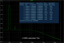
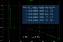
I tried 10 watts 1khz with 24volt rails and results are as attached - let me know if you think they look off.
BTW your 'test-bed' parameters and setup alone makes this asc well worth downloading ! Very efficient way of playing with spice. Thanks again.
Attachments
Lhquam,
Thank you that's very kind !
I added the models for the jfets to your asc and ran the sim and the results for your amp were very pretty indeed 😀 - i guess folks can try and retrofit and listen for preferences as well.
I tried 10 watts 1khz with 24volt rails and results are as attached - let me know if you think they look off.
BTW your 'test-bed' parameters and setup alone makes this asc well worth downloading ! Very efficient way of playing with spice. Thanks again.
Oops, I forgot to include the JFET models. I will provide an updated .asc file so that you are using the same models.
Your results appear to be better than I got with 17.6V rails. Be sure to check the MOSFET bias currents when you change various parameters. You must iteratively tweak the values of the parameters R5 and R8 to get the desired idle current. My results are with 1.3A.
Here is an update to the Spice files with JFET models. The MOSFET and JFET models are in separate .asc files.Here it is!
Attachments
Last edited:
No Smoke
I did some testing of a single unbalanced cascoded-output F5 without source resistors and with FQA28N15 and FQA36P15 MOSFETs. I attached the thermistors to the cascode MOSFETs since they dissipate most of the heat. I replaced R21 and R22 (the resistors in series with the thermistors in the updated F5 schematic in the F5-Turbo article) with potentiometers in order to tweak the thermal feedback stabilization loop. It looks like it is possible to stabilize it under no signal conditions, but the MOSFET currents make a huge jump with as little as a 1 Watt output signal.
Since these tests were done with current limited bench power supplies, I have not smoked anything. I am sure that the there would have been smoke had I used a fully capable amp power supply.
So far I have not been able to tweak the various adjustments to get the desired harmonic spectrum. I need to reintroduce selectable source resistors in order to turn the amplifier back into an ordinary F5 and redo measurements.
As a result of exploring the idea of completely eliminating the source resistors and using cascoding, I now have a much greater respect for Nelson's F5-Turbo which has the effect of reducing the source resistance at high power levels, but has manageable thermal and DC bias stability. I might look at the notion of cascoding the F5-Turbo outputs.
After performing these experiments
You start to get a real picture of just how much time he puts into one of his designs. Impressive really.
As a result of exploring the idea of completely eliminating the source resistors and using cascoding, I now have a much greater respect for Nelson's F5-Turbo which has the effect of reducing the source resistance at high power levels, but has manageable thermal and DC bias stability. I might look at the notion of cascoding the F5-Turbo outputs.
Why not just bypass the source resistor with a capacitor (Kasey Bypass Kapacitor hahah) ? Seriously though this is an old idea but havent seen it applied recently (perhaps for good reason?)
The voltage rating drop across the resistor is small so we can use one of them 6.3V super low esr motherboard capacitors. I bought some and intend to try. Seems to me that that would give us DC bias stability benefit of source R, plus square law characteristics of no source R. Spice simulations gives very good results and i think its a very worthwhile thing to try for anyone with a stock F5.
used organic polymers in recent amp. Cant say i heard them. DO yu want to hear diode or bypass cap. The diode does behave slighlty differently, doesnt it. It is more gradual than cap.
In order to not function as a high-pass filter, the capacitor would have to be on the order of 0.1F. ESR is also an issue.
Why not just bypass the source resistor with a capacitor (Kasey Bypass Kapacitor hahah) ? Seriously though this is an old idea but havent seen it applied recently (perhaps for good reason?)
The voltage rating drop across the resistor is small so we can use one of them 6.3V super low esr motherboard capacitors. I bought some and intend to try. Seems to me that that would give us DC bias stability benefit of source R, plus square law characteristics of no source R. Spice simulations gives very good results and i think its a very worthwhile thing to try for anyone with a stock F5.
Please leave a pointer to the other thread.i did some sims and move to another thread to discuss separately.
Apologies .... Here it is
http://www.diyaudio.com/forums/pass-labs/234809-bypass-caps-source-resistor-f5-example.html
http://www.diyaudio.com/forums/pass-labs/234809-bypass-caps-source-resistor-f5-example.html
Why not just bypass the source resistor with a capacitor (Kasey Bypass Kapacitor hahah) ? Seriously though this is an old idea but havent seen it applied recently (perhaps for good reason?)
The voltage rating drop across the resistor is small so we can use one of them 6.3V super low esr motherboard capacitors. I bought some and intend to try. Seems to me that that would give us DC bias stability benefit of source R, plus square law characteristics of no source R. Spice simulations gives very good results and i think its a very worthwhile thing to try for anyone with a stock F5.
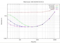
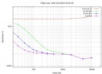
I have some simulations of your suggestion of adding capacitors across the source resistors. Here are two plots of THD in the Balanced F5 using FQA28N15 and FQA36P15 VFETs at 10 watts output into 8 ohms with various values for the caps: 0pF, 0.015F, 0.047F, and 0.10F. The first plot is without cascoding the output FETs; the second plot is with cascoding. The series resistance of these caps was 0.015 ohms, taken from datasheets of available low-Z caps. Because of the balanced F5 even order harmonic cancellation, THD data is totally dominated by the 3rd harmonic.
Obviously, the simulations indicate a path to lowering 3rd (and other odd order) harmonics while preserving the thermal stability provided by the source resistor. The next step for me is to order appropriate capacitors and bench test this modification.
Attachments
Absolutely rigorous analysis as always from you lhquam 🙂
The real world measurements may well be only half of what the sims suggest -
but the interesting thing in your simulations are the VERY significant difference in HF impact of the caps in the cascode vs non casc implementations.
What do you think thats attributable to, given the small difference (bw casc and no casc) for the no caps versions ?
Also I have some caps handy that might suit - if you pm me an address, i can drop them in the mail.
- Status
- Not open for further replies.
- Home
- Amplifiers
- Pass Labs
- Balanced F5 in a Small Footprint