The plate has both DC (100VDC) and AC voltages. This is normal. An AC meter will ignore the DC voltage.
Or you can measure after the output coupling capacitor, which blocks the plate DC voltage.
Or you can measure after the output coupling capacitor, which blocks the plate DC voltage.

okay here we go:
0 volume level
C2: 2.3mV
C1: 2.5mV
1/4 volume level
C2: 3.9mV
C1: 4.2mV
1/2 level
C2: 47mV
C1: 55.5mV
3/4 level
C2: 87.9mV
C1: 98.3mV
Full level
C2: 151.6mV
C1: 153.4mV
0 volume level
C2: 2.3mV
C1: 2.5mV
1/4 volume level
C2: 3.9mV
C1: 4.2mV
1/2 level
C2: 47mV
C1: 55.5mV
3/4 level
C2: 87.9mV
C1: 98.3mV
Full level
C2: 151.6mV
C1: 153.4mV
Well, that's within expectations for this unit. It could be better, but one channel is certainly not missing.
Circuit from the level control to the following tube output is ok.
Circuit from the level control to the following tube output is ok.
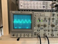
yep, wish this looked better, this is connected to the output, c2 dead flat. So at least we know it is good up to the plate. So for the novice brain (mine) the plate (anode) will begin the flow across the grid to the cathode? And is that were it passes to the next stage, from the cathode (conventional current flow - anode to cathode)?
I guess I am just trying to understand the signal flow in these 7247 tubes, I know they are dual triode but dissimilar, and I know we just checked one side...
I guess I am just trying to understand the signal flow in these 7247 tubes, I know they are dual triode but dissimilar, and I know we just checked one side...
Attachments
Last edited:
What do you mean by the output, what exact circuit node?
The signals were at both plates (the outputs) of the tube in your measurement.
The signals were at both plates (the outputs) of the tube in your measurement.
okay I guess by output I mean, where the signal comes into the 7247 and where it leaves. I am missing some fundamentals here for sure. I thought in conventional current from the flow will be from anode to cathode. So with the 7247, trying to understand I guess the signal path. I will have to study the schematic here for a sec. To me it looks like from the schematic the signal leaves the, yep, plate (anode) like you said and it goes across the pots for bass and treble and then back to the second triode's grid in the 7247 and i guess the same happens again.
In post #63, you measured signals at both plates. But the scope sees no waveform at one plate?
If you connect both probes to the same place, like one output,
do you see the same waveforms on each channel on the scope?
Are you sure the scope is working in both channels?
If you connect both probes to the same place, like one output,
do you see the same waveforms on each channel on the scope?
Are you sure the scope is working in both channels?
So the scope is connected at the point where my speaker outputs go to my dummy loads. Is that not the right way?
All of my voltage measurements above were with my DMM just probing the plate.
All of my voltage measurements above were with my DMM just probing the plate.
Connect the scope at the exact same place as the DVM probe.
It should be on AC coupling to block any DC present.
You have to measure the same thing if you expect to see the same thing.
If your scope works, you don't really need to use the DVM at all.
It should be on AC coupling to block any DC present.
You have to measure the same thing if you expect to see the same thing.
If your scope works, you don't really need to use the DVM at all.
No, you've already measured that. Go on the the following circuit block, after the tone controls.
The circuit blocks are all in series. You go forward from the first block to the second block to the third block, etc.
A bad measurement means the previous circuit block is bad.
Obviously one circuit block is bad, since there's no signal at the main output, after all the blocks.
The circuit blocks are all in series. You go forward from the first block to the second block to the third block, etc.
A bad measurement means the previous circuit block is bad.
Obviously one circuit block is bad, since there's no signal at the main output, after all the blocks.
Didn't take long, just for my sanity and practice 🙂
0 volume level
C2: 0.025V
C1: 0.025V
1/4 volume level
C2: 0.055V
C1: 0.055V
1/2 level
C2: 0.440V
C1: 0.450V
3/4 level
C2: 0.795V
C1: 0.810V
Full level
C2: 1.225V
C1: 1.215V
0 volume level
C2: 0.025V
C1: 0.025V
1/4 volume level
C2: 0.055V
C1: 0.055V
1/2 level
C2: 0.440V
C1: 0.450V
3/4 level
C2: 0.795V
C1: 0.810V
Full level
C2: 1.225V
C1: 1.215V
okay I will move along that signal path and report back but in theory everything you are saying makes perfect sense, let me just see if I can put it to the test using my brain and find it! Thank you again so much for your time. Let me check the other end of the 7247.No, you've already measured that. Go on the the following circuit block, after the tone controls.
The circuit blocks are all in series. You go forward from the first block to the second block to the third block, etc.
A bad measurement means the previous circuit block is bad.
Obviously one circuit block is bad, since there's no signal at the main output, after all the blocks.
Ok, you don't need to adjust the level control any more, that was only for testing the level control tracking.
Just set the level control to give a reasonable level, maybe halfway up, and leave it there.
Only check the signals at the plates. Some of the grids are virtual grounds, and are not data.
You do have to say at which node you are measuring, or the data are meaningless.
This is called "signal tracing", for obvious reasons.
okay sounds good, I appreciate that. So like I saw in the schematic, it looks like signal goes through the bass and treble controls and then back into the grid of the second side of the 7247 and then leaves the anode, would this be the next logical place to repeat?
Yes, at the plate (anode is for diodes).
The tone block grid is a virtual ground, and so a measurement is not needed.
This is because it is a feedback tone circuit.
You start at the input plate, and go forward, measuring at each plate, until the signal is gone.
Then the problem is just before or at that node.
The tone block grid is a virtual ground, and so a measurement is not needed.
This is because it is a feedback tone circuit.
You start at the input plate, and go forward, measuring at each plate, until the signal is gone.
Then the problem is just before or at that node.
Yes, the tone circuit block is the second circuit block after the level control that uses the 7247.
The first circuit block after the level control also uses the 7247, but just as an amplifier.
The first circuit block after the level control also uses the 7247, but just as an amplifier.
When I check the plate of the 12ax7 i get this
200mV going from 12ax7 to 6sn7 on channel 2
290mV going from 12ax7 to 6sn7 on channel 1
200mV going from 12ax7 to 6sn7 on channel 2
290mV going from 12ax7 to 6sn7 on channel 1
- Home
- Amplifiers
- Tubes / Valves
- Balance and bias voltage unstable