I shouldn't imply that the "piston in an infinite baffle" load is a total solution here. Obviously when the cone starts breaking into modes and, perhaps, starts to look like a smaller unit, then the model gets a little more complex. Suffice it to say that at higher frequencies the unit inevitably beams, its radiated power eventually rolls of approaching 12 dB/ Oct due to ka related matters, and electrical effects can be significant.
Regarding the latter, most popular full range units deal pretty well with the inductance thing and are within a few dB of full output at, say, 10kHz.
They still appear to have the same power response as non full range units, or lets at least say they are rolling off from the same frequencies at 30 and 45 degrees off axis.
Only on axis are they "full range".
David S.
I can agree with that.I shouldn't imply that the "piston in an infinite baffle" load is a total solution here. Obviously when the cone starts breaking into modes and, perhaps, starts to look like a smaller unit, then the model gets a little more complex. Suffice it to say that at higher frequencies the unit inevitably beams, its radiated power eventually rolls of approaching 12 dB/ Oct due to ka related matters, and electrical effects can be significant.
Indeed. It's all part of a delicate balancing act when the driver is designed. Some things try to make the axial response fall off at higher frequencies, others actually try to make it increase. Balance them against each other well and you can get a fairly flat response. (At least on axis)Regarding the latter, most popular full range units deal pretty well with the inductance thing and are within a few dB of full output at, say, 10kHz.
I'm not sure that I quite agree with that, or at least I don't think you meant to say power response ? (Maybe directivity index)They still appear to have the same power response as non full range units, or lets at least say they are rolling off from the same frequencies at 30 and 45 degrees off axis.
If you compare an 8" woofer that naturally rolls off at 3Khz with an 8" (single cone, paper dust cap) full range driver that rolls off at say 10Khz, the difference at high frequencies must surely be power response.
Both drivers will have a roughly comparable directivity index at all frequencies dictated by the size of the cones, perhaps modified a small amount by cone breakup modes and differences in specific geometry like depth, but not hugely different.
If the DI index is roughly the same and the on axis response extends much higher the power response must as well. The full range driver has more output in all directions at treble frequencies than the woofer, probably because the cone material/weight and VC/cone junction is better optimised to transmit high frequencies compared to the woofer.
If you're comparing it to a much smaller driver like a dome tweeter, then yes the power response will be way lower.
There are also a couple of exceptions to the DI index being roughly the same as a similar sized woofer though - whizzer cones and radiating dust caps. If a whizzer cone is half the diameter of the main cone in theory if it could be crossed over low enough it would extend the dispersion and power response by an octave.
In practice it generally doesn't work as well as it might, because its too difficult to cross it low enough. (It's hard to roll the main cone off fast enough, low enough) For example on my coral drivers the mechanical crossover is 5.6Khz but to extend the dispersion optimally it would really need to cross over at more like 2-3Khz.
Because it crosses over too high the dispersion falls off only a little bit better than an 8" woofer up to about 4Khz and then widens somewhat from 5-8Khz before narrowing again. (Too little too late - its not fully crossed over until the smaller cone is itself also starting to beam somewhat)
What improvement there is in dispersion below 4Khz seems to come primarily from the whizzer cone acting as a phase plug sitting in front of the main cone. (It decreases the on axis response and increases the off axis response by a few dB above about 2Khz)
Most whizzer cone drivers cross over even higher. (For example the Fostex FE207E whizzer crosses over at around 7Khz) Perhaps a really lossy main cone could get the cone to roll off by itself at 2-3Khz and therefore cross over lower with much improved dispersion...
The other thing is a radiating dust cap, and this really does work. Any full range driver whose treble extension comes from a radiating dust cap will see an increase in dispersion as well as an on-axis increase provided that the dust cap is tightly coupled to the voice coil and loosely coupled to the cone so that its the primary radiator at high frequencies.
Treble power response will be significantly better than an equalised woofer but still far short of a dome tweeter.
The difference in off axis treble response between my Corals (with aluminium radiating dust caps) vs the Fostex (paper dust cap) is quite stark. 20 degrees off axis you can still hear 10-15Khz treble on the Coral, you hear nothing in the treble at that angle from the Fostex...
Again the problem for getting optimal results from the dust cap is crossing over too high from the previous cone. The whizzer cone won't give up until 10-12Khz so it's only above that that the dust cap can radiate only on its own and widen the dispersion. A radiating dust cap may cross over better on a single cone driver because the cone will roll off lower than a smaller whizzer cone would, thus leaving the dust cap to do its own thing at the top end without interference.
Of course. Lucky that the direct field is so predominate in our perception of treble then isn't it 😉 Otherwise a full range driver would be a complete write off. The fact that a full range driver can still sound surprisingly good despite the huge increase in DI in the treble is a testament to just how dominant the direct field is at treble frequencies. (Yes its not ideal, and yes the reverberant field can sound a bit dead at high frequencies with such a setup, I prefer a tweeter)Only on axis are they "full range".
Last edited:
Originally Posted by weltersys
Tom Danley’s Bdeap 4 box array with an on axis sensitivity of 117.5 dB SPL with 1 electrical watt at 1 meter, measured in half space has what I would call significant LF directivity, 5.5 dB over 1 acoustic watt, which you wrote is 112dB for a half space hemispheric source.
They do have high Q to a much lower frequency than the 90 x 90 inch frontal area (22.5 inch deep) would suggest, the woofer arrays in the Gander paper you linked have more frontal area but much lower Q.
Art
Tom Danley’s Bdeap 4 box array with an on axis sensitivity of 117.5 dB SPL with 1 electrical watt at 1 meter, measured in half space has what I would call significant LF directivity, 5.5 dB over 1 acoustic watt, which you wrote is 112dB for a half space hemispheric source.
It seems to me that many of your statements regarding efficiency should use the term sensitivity, taken in terms of efficiency, four Bdeaps would be an over unity (AKA perpetual motion) device, while in reality they are a high Q device.Stick a sensitive microphone in front of it and feed it back to the driver's input: Voila! Perpetual motion!😉
David
They do have high Q to a much lower frequency than the 90 x 90 inch frontal area (22.5 inch deep) would suggest, the woofer arrays in the Gander paper you linked have more frontal area but much lower Q.
Art
Perhaps I overstate it but most of the full range units I see do a credible job on axis but don't extend much, if any at off axis angles compared to more conventional drivers. I agreed that some whizzer cone or radiating dome/decoupled cone units might be exceptions.I'm not sure that I quite agree with that, or at least I don't think you meant to say power response ? (Maybe directivity index)
If you compare an 8" woofer that naturally rolls off at 3Khz with an 8" (single cone, paper dust cap) full range driver that rolls off at say 10Khz, the difference at high frequencies must surely be power response.
To me that would mean that the full range and the conventional units power responses were closer than their on-axis responses would indicate. Again, an 8" unit has a predefined 2nd order rolloff frequency inherent in its radiation load, unless it can get past the limitations of its basic diameter.
I'm not against full range units, by the way. I appreciate the Zen like simplicity of the concept. I probably spend more of my day listening to 1 way systems (NPR on various AM radios).
Of course. Lucky that the direct field is so predominate in our perception of treble then isn't it 😉
Who told you such trash!😀
David
It seems to me that many of your statements regarding efficiency should use the term sensitivity, taken in terms of efficiency, four Bdeaps would be an over unity (AKA perpetual motion) device, while in reality they are a high Q device.
They do have high Q to a much lower frequency than the 90 x 90 inch frontal area (22.5 inch deep) would suggest, the woofer arrays in the Gander paper you linked have more frontal area but much lower Q.
Art
I hope I keep the distinction straight, at least most of the time. Thats why the comment on your 117 dB sensitivity. I knew it was beyond the 1 watt out for 1 watt in point and so had to be a product of high directivity.
Note that the Keele paper I referenced above shows that 25% efficiency is the max to be expected from non-horn systems (horns can hit a theoretical 50%). That would limit you to 106 in 2pi. So this system has a d.i. of 11dB or more?
David
NOW, the effect of "beaming" seems like the next logical turn for this thread. Beaming (correct me since I am probably wrong here) seems to be a function of piston radius and frequency. As far as I can tell, it doesn't matter if the driver is in free space or half space. Maybe Beranek covers this...I haven't gotten that far yet though.
Yup, "beaming" is mainly a function of frequency and piston radius (ka).
But, interestingly enough, even at ka=3, the piston evidently can "feel" whether or not there is a baffle around it.
By ka=4 this ceases to be the case.
Attachments

An on axis sensitivity of 117.5 dB SPL with 1 electrical watt at 1 meter, measured in half space, I don't know the d.i. (directivity index ?) number, or specific frequency range the sensitivity was achieved at.I hope I keep the distinction straight, at least most of the time. Thats why the comment on your 117 dB sensitivity. I knew it was beyond the 1 watt out for 1 watt in point and so had to be a product of high directivity.
Note that the Keele paper I referenced above shows that 25% efficiency is the max to be expected from non-horn systems (horns can hit a theoretical 50%). That would limit you to 106 in 2pi. So this system has a d.i. of 11dB or more?
David
Tom Danley has written that bass horns actually can achieve higher efficiency than high horns.
I built a lot of very narrow dispersion horns, dubbed the Maltese horn
Using a run of the mill Eminence PSD2002, they do over 115 dB 1w 1m from 2-6K (and one spike at 11K).
I thought that was ground-breaking performance, but as Bob Oswood said to me in 1992, speaking classic Minnesotan :
"some guys would just say you made a beamy horn" .
Art
Yup, "beaming" is mainly a function of frequency and piston radius (ka).
But, interestingly enough, even at ka=3, the piston evidently can "feel" whether or not there is a baffle around it.
By ka=4 this ceases to be the case.
Yes, when the driver gets directional enough it stops "illuminating" the cabinet edges. At that point the 4pi to 2pi transition must be complete.
Note the beloved dipole. d.i. of 4.8 at low frequencies and it stays low when the others rise, primarily because it is firing both ways.
David S.
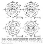
Surely a dipole constructed of dynamic drivers on a baffle must also start beaming at high frequencies and thus increase its overall DI above 4.8dB ? The dipole configuration just sets a lower DI limit of 4.8dB while a monopole eventually falls to 0dB well below its baffle step frequency.Note the beloved dipole. d.i. of 4.8 at low frequencies and it stays low when the others rise, primarily because it is firing both ways.
Edit: The image bolserst attached does seem to show this, I just realised that "unbaffled piston" in the top right graph refers to a dipole, showing that above a ka of 2 it does rise but not as much as the other cases.
I presume that graph assumes symmetrical high frequency radiation from the front and rear of the dipole too, which wouldn't be the case with a dynamic driver where most high frequencies would be front firing only, so practically speaking a dynamic driver dipole could still attain quite high DI at high frequencies, and higher than that line would suggest. A symmetric ribbon dipole would probably more closely match the theoretical figures.
Last edited:
Yup, "beaming" is mainly a function of frequency and piston radius (ka).
But, interestingly enough, even at ka=3, the piston evidently can "feel" whether or not there is a baffle around it.
By ka=4 this ceases to be the case.
Man, I took a long "break" (6+ months) from working through Beranek about 3 pages shy of this. Use it or lose it I guess...beaming isn't as mysterious as I thought. Time to dig out my notebook & try to finish part X.
Thank you to the folks posting links to technical papers. It is really interesting stuff. Sorry I can't contribute more. I am definitely the "student" in these discussions!
Surely a dipole constructed of dynamic drivers on a baffle must also start beaming at high frequencies and thus increase its overall DI above 4.8dB ? The dipole configuration just sets a lower DI limit of 4.8dB while a monopole eventually falls to 0dB well below its baffle step frequency.
Edit: The image bolserst attached does seem to show this, I just realised that "unbaffled piston" in the top right graph refers to a dipole, showing that above a ka of 2 it does rise but not as much as the other cases.
That was my take on it, that the unbaffled piston narrowed essentially the same as the baffled piston but directivity would be based on both forward and backwards beams. I don't think "transduction principle" has anything to do with dirctivity.
Note that the text books will say in small print that every driver has twice the air loads shown (not dipoles, of course) but the rear radiation is ignored because it is absorbed within whatever cabinet form is used. You can get away with this if the air load is insignificant, but Keele implys it isn't, giving 1dB error at 0.6% efficiency.
David
Sorry I can't contribute more. I am definitely the "student" in these discussions!
I don't know, I couldn't sleep this morning so pulled out my copy of Beranek and started at Chapter 1. Introduction and Terminology. I kept thinking: "why don't I know this stuff?"
We are all students.
David S.
If you look closer at the radiation patterns for infinite baffle and piston at the end of a pipe you will see that as low as ka=2 the baffle is felt. Look at the 90 degree level. With infinite baffle it is down about 5dB, When at the end of a pipe it is down 10dB.
Also, it should be recognized that these polar plots and "beaming" assume that the observation point is far from the source. Thing change as the observation point gets closer, but that makes these analytical solution difficult to obtain. Thus we always see the simplifications that the distance is large compared to source size.
Also, it should be recognized that these polar plots and "beaming" assume that the observation point is far from the source. Thing change as the observation point gets closer, but that makes these analytical solution difficult to obtain. Thus we always see the simplifications that the distance is large compared to source size.
Uh, failing to account for diffraction of adjacent drivers is a problem with the modelling, surely ?
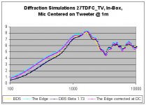
Thanks for helping to prove my point for me anyway, as apparently even the best simulator of the 3 tested has an error magnitude of +/- 1.5 dB through the transition region, (+/- 2dB for the worst one) which is pretty high when you consider the overall transition is only 6dB, that error magnitude is far too high to design a crossover against without measurement.
It would have been helpful if we could have seen the actual measured response and simulated response overlaid rather than just a differential error so that we could see the true nature of the errors.
For example the fact that the error deviation went negative then positive by a similar amount through the transition region suggests that the slope and/or the corner point for the transition was incorrectly calculated.
Likewise in the region above 2Khz we don't know what the source of the error is from only an error difference graph. My guess is that the simulation predicted narrow band ripples that simply failed to materialize in the measurement due to a simplified (or non existent) geometrical driver model that failed to predict the correct driver directivity.
As I've said on other threads discussing similar points, its a useful "first pass" to simulate possible "what if" cabinet scenarios but its not accurate enough to design a crossover against without measuring the driver on the actual baffle.
I find this comment interesting in the ARTA application note where it discusses how to merge a near-field response with a far-field response, and the "simplistic" (non-geometrical) baffle step estimation used in ARTA:
"Note: ARTA and STEPS uses the previous expression for the estimation of the diffraction for spherical
or rectangular baffled boxes. Some CAD and simulation programs are using a high-frequency
geometrical model for the estimation of box diffraction at low frequencies. Such models can give
larger errors on low frequencies than the simple model that is presented here. "
http://www.fesb.hr/~mateljan/arta/AppNotes/AP4_FreeField-Rev03eng.pdf
Ivo is a pretty smart guy, and yet seems skeptical of the accuracy of current geometric baffle step models...
Nothing replaces direct measurements, that's the truth! These tools allow experimenting with different driver placements and baffle shapes before cutting wood. I'm not sure I prove your point though, you're putting too much faith in my analysis. 🙂
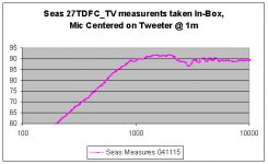
I think I should better explain my analysis. Bjorn at Seas provided a wealth of data for drivers measured in the Seas test box, within their anechoic chamber. He also provided data for a 27 TDFC-TV measured on a 60x80 baffle, in their anechoic chamber. All mounting and measurement coordinates were provided, along with Seas test box dimensions.
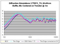
My analysis "backed out" the 60x80 measure to a theoretical 2 PI, using model predictions. Three popular free diffraction modeling tools were compared. I then "added in" a model of the diffraction in the test box and superimposed this on the 2pi estimate, to arrive at a predicted "in - box" curve. This was then compared to the actual in-box curve. So, some comments on the sources of error. I'm not convinced these are necessarily due to the modeling tools, but some may reside in the measurement or analysis.
1. There were two opportunities for the model to introduce error, once in the 60x80 baffle simulation, once in the box simulation. Was this error additive or subtractive with itself? I believe it was subtractive (ie nulling out), but that involves too much thinking for a Saturday morning
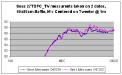
2. Bjorn took the 60x80 baffle measurements and provided them to me for this analysis. It's not certain that he used the same tweeter in the test box as in the baffle. I believe he did, and that was the intent, but needed to take this on faith since no serial numbers were provided. You can see that turn-over point and slope error creeps in below 800 Hz. This could very well be measurement error caused by using two different tweeters for baffle and box measures with different fs’s. The tweeter fs is in the 800Hz range. If two different tweeters were used, this could also explain the high frequency error. For example, see the comparison of the two different on baffle measures taken on different dates in the attached. I speculated that high frequency error was due to the presence of an adjacent woofer, but have no way to verify that. Using a different tweeter in each measure may have caused the error. This analysis is several years old now and there’s no way to understand if the same tweeter was used for both measures
3. These diffraction-modeling tools only assume the baffle dimensions, and have no accounting for the box depth. At low frequencies the box depth must impact the diffraction signature as the wave wraps around and re-diffracts off the rear corners of the box. Perhaps this is what Ivo was alluding to in his comment that a sphere or rectangular box was more accurate at low frequencies. However, without an anechoic chamber or outdoors to measure in, I can only speculate on the magnitude of this error.
Given these caveats, I would use these tools for modeling just below and upwards of the baffle diffraction peak, without hesitation. I don't have enough data to truly understand their accuracy down to the dB several octaves below the diffraction peak. I am however confident that they are accurate enough to take a near field measure, add the diffraction signature on top, and then splice to quasi anechoic results at ~ 300 Hz.
These also don’t model diffraction off adjacent drivers, which could be appreciable so prudent mounting geometry and final measurements are always warranted. There are ways to reduce this with felt (see my JR rebuild attached) but not everyone likes the look of a speaker with a mustache! It’s my Movember speaker. 🙂
Finally, an observation about the models themselves: The Edge has a fundamental error in one of its model assumptions.
The Edge always assumes + 6dB asymptotic baffle gain at high frequencies. This is only true in the far field. In the nearer field (eg 1m, even 2m) it can be less than this. The error is larger for larger baffle sizes (i.e. the larger the baffle, the further out the mic needs to be placed in order to be in the true far field). The DBS and the BDS don't have this error as they both correctly assume 0 dB baffle gain as the frequency asymptotes to DC. On an IEC baffle, The Edge incorrectly models over half a dB baffle gain as the frequency approaches DC.
I personally would chose either of the other two over the Edge if I was taking the leap of faith to use this to model BDC and not just signature at and above the dipole peak.
Dave
Attachments
Also, it should be recognized that these polar plots and "beaming" assume that the observation point is far from the source. Thing change as the observation point gets closer, but that makes these analytical solution difficult to obtain. Thus we always see the simplifications that the distance is large compared to source size.
Yeah, I really should have stated the simplifying assumption used in the calculations that produced the plots published in Beranek.
Perfectly rigid piston radiator driven with constant velocity(ie independent of frequency) and measured at an infinite distance.
For completeness, I should have also included the directivity patterns for the unbaffled piston(ie dipole)...attached below.
I heard recently that Tim Mellow is working with Leo Beranek to update his 1954 book ACOUSTICS which will contain a new chapter on sound radiation. It will be published by Elsevier some time next year perhaps.
Tim Mellow has published several papers on sound radiation both for rigid piston and membrane radiators, in free space, infinite baffles, and finite baffles.
Tim Mellow - United Kingdom | LinkedIn
http://asadl.org/jasa/search?sortby...ossible1zone=author&alias=/jasa&displayid=ASA
Attachments
Last edited:
We are all students.
Many is the time I've spent all day (e.g. while driving) analysing something like this at its fundamental level only to summarise it into applied knowledge, make plans with it, and promptly forget all the good stuff I thought I knew. 😉
I heard recently that Tim Mellow is working with Leo Beranek to update his 1954 book ACOUSTICS which will contain a new chapter on sound radiation. It will be published by Elsevier some time next year perhaps.
Looks like the update to the ACOUSTICS text is close to release:
Acoustics: Sound Fields and Transducers: Leo L. Beranek,Tim Mellow: 9780123914217: Amazon.com: Books
- Status
- Not open for further replies.
- Home
- Loudspeakers
- Multi-Way
- Baffle Step Loss - Why 6dB?