Thanks for the response.
I understand it is not scientific at all, but I just listen to the change made.
To avoid all that psychoacoustics magic around, I listen to the given solution for a couple of days and then switch to another solution.
It is fun 😊.
I understand it is not scientific at all, but I just listen to the change made.
To avoid all that psychoacoustics magic around, I listen to the given solution for a couple of days and then switch to another solution.
It is fun 😊.
That is OK 😉
Then if you have a full range driver with no other crossover components, then RC impedance flattening with RL baffle step circuit can be done that way.
Then if you have a full range driver with no other crossover components, then RC impedance flattening with RL baffle step circuit can be done that way.
Thanks for suggestion Norman.
I did some reading and found out something called Zobel network. It flattens out impedance curve meaning BSC filter should work better (its effect should vanish slower as impedance would grow slower). Some even advised to just put resistor in parallel with the driver.
But I am not sure if that would work and what another issues it would cause.
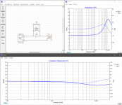
What people do to tame the top end, is an LRC filter in series with the driver, not just a resistor, but a reisistor, capacitor and inductor in parallel with each other in series with the driver, that creates a notch filter to tame peaks. The value of the capacitor and the inductor determines what frequency zone is cut down, the resistor how much. I attached an example (on a fixed impendance not existing driver) as example.
Attachments

Thanks for providing solutions, guys.
I will first try to employ zobel network to see (hear 😊) what happens.
Then I may want to try more complex solutions if zobel does not solve the issue.
Anyway, if I wanted to use some simulation program like xsim, I would need zma/frd files, but they are not provided on mark audio web page. Just plots that are difficult to process.
Thanks for the favor Allen.
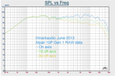
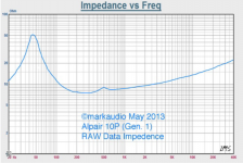
I am wondering how you do that. The specialized and very robust image processing program would be needed for that. I am just attaching the images extracted from the pdf provided here:
https://www.kjfaudio.com/wp-content/uploads/2017/02/Alpair_10P_Gen.1.pdf
You can see x and y axes are not linear/equidistant and the graphs include the text that needs to be ruled out in case of impedance or even taken into account in case of frequency response file.
Attachments
For 8ohm speakers in typical 8in to 10in wide baffles, my go-to standard starting point is a 1mH coil and about 4.7ohms 10w in parallel. That can be added to the outside of the speaker using Wago connectors and adjust the resistor to taste. For more bass, use 6.8ohm, for more sparkle use 3.3ohm etc. adjust to taste. Either air core or iron core can work here. Sometimes I have used 0.8mH or even 0.68mH of you want to move the beginning of the shelf up higher. For 1mH it’s around 800Hz to 900Hz. Just try it and you will hear a difference immediately. Then measure it with REW and a calibrated mic.
Vituixcad and fp graph tracer will attempt automatic tracing, and SPL-trace gives you more control for the difficult ones.
Did you want the 15 and 30 degree files?
Many thanks for the files. I am just OK with the on-axis response file. I will have to try Vituixcad myself (if it works in Wine on Linux). Already tried XSim and it works so can try to import the files 🙂 .
For 8ohm speakers in typical 8in to 10in wide baffles, my go-to standard starting point is a 1mH coil and about 4.7ohms 10w in parallel. That can be added to the outside of the speaker using Wago connectors and adjust the resistor to taste. For more bass, use 6.8ohm, for more sparkle use 3.3ohm etc. adjust to taste. Either air core or iron core can work here. Sometimes I have used 0.8mH or even 0.68mH of you want to move the beginning of the shelf up higher. For 1mH it’s around 800Hz to 900Hz. Just try it and you will hear a difference immediately. Then measure it with REW and a calibrated mic.
I already tried BSC filter with 6.8 ohm resistor and 1.5mH coil and think the resistor value is the correct one. Not sure about the inductor value and want to try coils with lower inductance once I get them.
Not sure about the measurements. This is my first speaker and don't want to split my attention.
And thanks for the hint with wago clips. I was using clothes pins and think it is time for upgrade 😀.
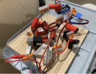
1.5mH is a bit too much. You can always unwind the coils if you need to. Wago is fantastic. It lets me build a complex prototype XO in 10 minutes. It sounds good too. Very secure connections. No soldering or strip panels needed. All P2P with connectors.
Here is a very “Wago’d out XO” I just mad the other day.
Attachments
25 piece kit for $14 is enough to build just about any XO.
Wago Transparent 2,3,5 Splicing Wire Connector, Lever-Nuts Terminal Block (25pc) | eBay
Wago Transparent 2,3,5 Splicing Wire Connector, Lever-Nuts Terminal Block (25pc) | eBay
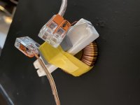
I got some wago connectors and it is much easier to switch components in a filter.
My final parallel lrc in series with the driver is 0.5 mH, 10 ohm and 1uF.
I am happy with the sound. Next time will try to build pensils with the same driver.
My final parallel lrc in series with the driver is 0.5 mH, 10 ohm and 1uF.
I am happy with the sound. Next time will try to build pensils with the same driver.
Attachments
Nice. Be careful with small toroidal inductors like that. They can saturate if your amp is putting out any DC. Straight iron core or air core is better.
Do you think I should replace the inductor? I was rather not sure about the quality of the very cheap capacitor.
How could DC occur on speaker terminals? Do you mean DC as a result of amplifier misbehavior or as an average of AC wave (e.g. propagated ftom the mains)?
Thanks.
How could DC occur on speaker terminals? Do you mean DC as a result of amplifier misbehavior or as an average of AC wave (e.g. propagated ftom the mains)?
Thanks.
Yes, most DC coupled output amps have some level of DC (5-20mV). Very well behaved ones are close to 0mV.
But in general the inductors like you show are for power supply filtering. You might want something designed for audio. That’s not to say not cannot work, as you can hear it improved the sound from what you had.
Like these…
Iron core, compact, low cost, low DCR, good performer:
Dayton Audio 1.0mH 18 AWG I Core Inductor Crossover Coil
Or air core - cannot saturate and very low distortion, but higher DCR and more expensive:
Jantzen Audio 1.1mH 18 AWG Air Core Inductor Crossover Coil
I got the components for audio applications from the dexon company ( the local, czech one) and rebuilt the filter. Difficult to say if there is any difference. Maybe yes, maybe no. Anyway, the speaker sounds just great and beats elacs debut 5.2 I have for comparison in every way.
Attachments
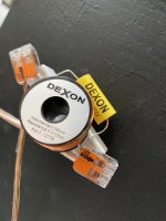
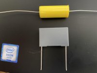
Comparison of cspacigors
I cannot hear the difference when switching the air core and iron core inductors with the same value. But found out that switching capacitors (cheap one vs more expensive one) makes difference. The yellow one (in the picture) costs one dollar and sounds quite bright compared to grey one which costs just 50 cents. In fact, I like the sound of cheaper capacitor more.
Looking into the specs, the yellow capacitor is marked with mkt while the grey capacitor is marked mkp 62. Both have capacity around 950 nF (measured with multimeter).
Not sure what conclusion can be made as there are probably too many external variables in this test.
Attachments
- Home
- Loudspeakers
- Full Range
- Baffle step compensation circuit for bookshelf speaker