I don't know why people don't use felt or foam around tweeter, between tweet / woof.
Your intuition would be at home with Wilson Audio
Attachments
and monitors for recording...………………………...
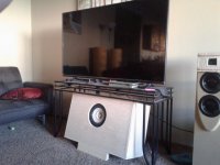
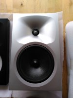
felt around morel dome tweet (solstice kit)
on right edge of picture
felt around morel dome tweet (solstice kit)
on right edge of picture
Attachments
Last edited:
to make it extremely lightweight and portable
Composites. A PR is really only for too small a box tuned very low. I haven’t looked at the Purifi, i know X is stoked about it. I avoid PRs.
Here, 25 litres is a bigger box. But my biggest one is coming, 400Litres.
dave
🙂 Chamfers can be very effective, a series of 30 degree chamfers are almost as good as a curve. This is a useful toy to get a feel for how waves behave Ripple Tank Simulation
Definitely moving toward the big chamfer/radius direction after these convos.
That ripple sim made me a little queasy btw. Too bad you can drop a cross section of a baffle in that baby-
Composites. A PR is really only for too small a box tuned very low. I haven’t looked at the Purifi, i know X is stoked about it. I avoid PRs.
Here, 25 litres is a bigger box. But my biggest one is coming, 400Litres.
dave
5/16 wide, ribbed monocoque with carbon skins . IIRC should be about 4x stiffer than 1" mdf. I chose 25L due to the Purifi Vas spec as well as the recommendations for the SEAS 8" PR, which will tune to 30Hz @ 30 Liters. I'm just following the spec. trail, as it were. I like the PR option for it's tidiness and ease of implementation.
X? If that is the same X that did the TL build, I am definitely following his stuff on the Purifi closely. Am in a convo about TL/crossover with him, but atm, the TL stuff is a bit more complexity, construction wise, than I want to take on for the first go around.
For whatever reason I have assumed that a narrow/deep cab performed better than a wide/shallow one.
A narrow baffle places the secondary sources close to the driver, horizontally at least, which mitigates the negative effect on imaging to a degree.
and monitors for recording...………………………...
felt around morel dome tweet (solstice kit)
on right edge of picture
Yours? What sort of effect did it have?
A narrow baffle places the secondary sources close to the driver, horizontally at least, which mitigates the negative effect on imaging to a degree.
Ok, can you elaborate a little bit on this? Where I thought you were gonna go was that a wide/shallow baffle/box was problematic internally due to reflectivity issues onto the driver, whereas a deeper cab will be easier to manage that problem.
But your saying that a narrow baffle/cab has external advantages over the wide baffle? Not sure what you mean by secondary sources, reflections off the baffle? If I'm understanding this, a wide baffle will possibly suffer imaging degradation as opposed to the more narrow style like I have been working on.

better detail
here is a quick read with graphs...………….
Diffraction Doesn't Have to be a Problem
1/2" felt helped down to 1.1khz
I recommend f10 1/2" near $25 on amazon for a 12" x 12"
here is a quick read with graphs...………….
Diffraction Doesn't Have to be a Problem
1/2" felt helped down to 1.1khz
I recommend f10 1/2" near $25 on amazon for a 12" x 12"
Actually, this is very much in line with certain things I was going for. Stepped baffle- check. Felt surround- check. One of the biggest criticisms I've taken onboard so far is the problem of having the uniform circular edge, as I have seen this measured in detail elsewhere.
My 1/16" felt inserts are clearly inadequate having read through your material. With some slight modifications, such as increasing the felt insert pocket depth to .48 inches I can use the correct material and have a slight overhang of the felt by .020". Instead of the standard edge radius, I can make it asymmetrical and make it almost non existent where it meets the felt.
The stepped baffle portion is being adjusted to be widened to handle either a larger radius or a 30deg to 45deg progressive chamfer.
Finally, I'm looking at ways to breakup the circular/symmetrical nature of the step, either through faceting or some other means. Given my 8 x 18" constraints, I tend to believe that felt or some similar treatment is likely part of the better solutions available. Trying to implement it in a way that looks pleasing seems to be the biggest challenge.
When I think of very light, and very stiff, something that rings comes to mind.
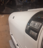
I have seen a velvet like material, or flocking used to help tame baffle diffraction on some very nice speakers, and am looking at buying some to try in a couple spots on the edge of my car’s dashboard. I certainly won’t be applying any 1/2” felt that looks like a diaper on my dash, so it’s either something like the self adhesive flocking or forget it altogether.
I have seen a velvet like material, or flocking used to help tame baffle diffraction on some very nice speakers, and am looking at buying some to try in a couple spots on the edge of my car’s dashboard. I certainly won’t be applying any 1/2” felt that looks like a diaper on my dash, so it’s either something like the self adhesive flocking or forget it altogether.
Lol. C'mon, a fat slab of felt would look totally rad! Fortunately the way the baffle in question is setup, it'll more or less set flush in milled out pockets.
Very interesting points you bring up...light plus stiff = ringing. I definitely think it has a lot of potential to do something, let's say, weird 😀
Matching the stiffness to that of 3/4 mdf should be pretty straightforward. Just make the panels thinner or use fewer plies. I planned on using a PR, so perhaps that extra stiffness might also be managed that way. I'm assuming it's doable based on some of the nosebleed high-end stuff out there. Magico has their flagship model that is basically carbon skins on an aluminum honeycomb core.
On weight, I plan to replace all of the savings with added features, such as battery power, amps, etc. Each amp/speaker combo will come with about 600-1000 watts of LTO batteries, so the pack weight alone would makeup for the absence. My assumption is that the cabinet would have to be tuned (if needed) using weights (amps/batts), much like a helicopter is tuned by adjusting weights on the vibe absorbers. Just a theory. But I am excited to find out. But seriously, 1/2 slabs of felt on the dash lmao
When I think of very light, and very stiff, something that rings comes to mind.
A foamcore build can be done that is both very stiff, very light, and constrained layer.
dave
That is “sharp” at the edges.
Curves need to really be 3-4” in radius to be effective at amything but the highest frequencies. No sharp edges. What sharp means depends on the frequency you are talking about.
What you have shown so far reminds me of some of the molded baffles on big boomboxes solely to look impressive or different.
dave
I was going for less boombox and more Hewlett Packard 😉
Attachments
Okay, I'm a little deeper into the gritty details, based on several comments. Thanks so much everybody chiming in!
I want to first address the stepped driver group for being likely to cause excessive diffraction. This will be the first surface to make contact directly from the driver.
1) One argument is that the ring geometry is bad for diffraction and I have read this elsewhere too.
2) Another argument is that the B&W 802 curve profile is only effective because it is a continuous path (paraphrasing). My sliced B&W-esque step will not act as it does on the 802 because the path is not continued.
3) The sharp step of the driver group will diffract because there needs to be a large curve/chamfer, i.e. gradual transition.
I think these are good points and I tend to agree, or would at least say they make sense. More scrutiny as regards comparing my driver group with the 802 does, however, reveal what may be some logical fallacies.
1) If the transition need be gradual, such as a big radius, then the 802 has failed there, same as my iteration. This transition is what I consider to be the first encounter, post driver, for the wave to contact. In my case the abrupt drop off. In B&W's case, the abrupt drop off.
2) Continuing past the 'first contact,' my group terminates into a flat surface where another set of solutions is being discussed; 1/2" thick felt inlays. The 802 continues the profile on to the rear of the cabinet, hence why the 802 works to reduce diffraction. Here though, the more I study the 802, the more I have doubts about it's seamless geometry. There are several positions around the teardrop that fail to maintain continuity.
3) If it can be said the 802 discontinuities are marginal because they are down stream of the first contact surface, then should this not place emphasis on the first contact as being the key contributor to diffraction? Now to compare my specific group geometry, at the first contact location, to that of the 802's teardrop profile, it can be shown that the profiles are very comparable.
Finally, when those factors are taken into account, I make the argument that one of two assertions should be more or less correct. That either 1) the 802 has bad geometry at the first contact surface, for the same reason that my design is bad for diffraction at the first contact. Or 2) that my initial profile is good because the 802 profile is good.
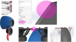
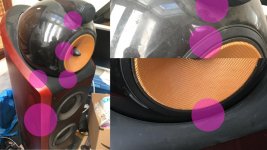
To back up what I am saying I'll add some visual reference comparing my stepped group to the teardrop. Also, I point out locations on the 802 that do not hold up to being perfectly optimal. In my opinion, of course.
I want to first address the stepped driver group for being likely to cause excessive diffraction. This will be the first surface to make contact directly from the driver.
1) One argument is that the ring geometry is bad for diffraction and I have read this elsewhere too.
2) Another argument is that the B&W 802 curve profile is only effective because it is a continuous path (paraphrasing). My sliced B&W-esque step will not act as it does on the 802 because the path is not continued.
3) The sharp step of the driver group will diffract because there needs to be a large curve/chamfer, i.e. gradual transition.
I think these are good points and I tend to agree, or would at least say they make sense. More scrutiny as regards comparing my driver group with the 802 does, however, reveal what may be some logical fallacies.
1) If the transition need be gradual, such as a big radius, then the 802 has failed there, same as my iteration. This transition is what I consider to be the first encounter, post driver, for the wave to contact. In my case the abrupt drop off. In B&W's case, the abrupt drop off.
2) Continuing past the 'first contact,' my group terminates into a flat surface where another set of solutions is being discussed; 1/2" thick felt inlays. The 802 continues the profile on to the rear of the cabinet, hence why the 802 works to reduce diffraction. Here though, the more I study the 802, the more I have doubts about it's seamless geometry. There are several positions around the teardrop that fail to maintain continuity.
3) If it can be said the 802 discontinuities are marginal because they are down stream of the first contact surface, then should this not place emphasis on the first contact as being the key contributor to diffraction? Now to compare my specific group geometry, at the first contact location, to that of the 802's teardrop profile, it can be shown that the profiles are very comparable.
Finally, when those factors are taken into account, I make the argument that one of two assertions should be more or less correct. That either 1) the 802 has bad geometry at the first contact surface, for the same reason that my design is bad for diffraction at the first contact. Or 2) that my initial profile is good because the 802 profile is good.
To back up what I am saying I'll add some visual reference comparing my stepped group to the teardrop. Also, I point out locations on the 802 that do not hold up to being perfectly optimal. In my opinion, of course.
Attachments
Actually a shallow box can have the advantage of shifting the reflections of some of the internal waves up in frequency and make them easier to absorb.Where I thought you were gonna go was that a wide/shallow baffle/box was problematic internally due to reflectivity issues onto the driver, whereas a deeper cab will be easier to manage that problem.
- Home
- Loudspeakers
- Multi-Way
- Baffle Design....Diffraction and Crammed Tweeter?