BAF2015 Amplifier - A SIT Mu Follower, Revisited with Feedback
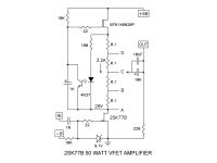
In 2019 I built the SIT version of the BAF2015 amplifier, with the THF-51S as the active device. At that time, that was my third solid state amp build. It started with the original diyAudio Sony VFET amp, a push-pull amp, then my second was the Michael Rothacher choke loaded L'Amp with 2SJ28.
The 2015BAF amplifier was a common source mu follower and with a 60VDC or so power supply. Being common source and mostly single ended, it also had a good amount of distortion, with second harmonic dominant. I was good with that, as I had diyed single ended triode amplifiers and preamps before getting into solid state, and they had a good amount of distortion, also second harmonic dominant, and I enjoyed that sound.
However over time I got into common drain SIT/VFET amplifiers and I realized that I preferred their lower distortion. Their distortion was still second harmonic dominant, but to my ears the lower distortion allowed for more clarity and realism in the sound. So my common source amplifiers got converted to common drain.
Recently I read diyAudio member ra7's post about the upcoming FW SIT-4 with feedback to lower distortion, and his positive experience with adding feedback to his choke loaded common source SIT amplifier.
https://www.diyaudio.com/community/...et-tdv-amp-using-2sk2087c.388926/post-7554089
So I thought, I am going to give feedback a try. Instead of Rahul's choke loaded version, I will add feedback to Nelson's BAF2015 SIT amplifier.
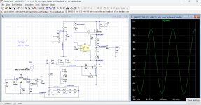
Adding feedback, the resistors in the feedback network increases the input impedance of the amplifier, which is also seen by the SIT. Combined with the SIT's high gate capacitance, that negatively affects the low frequency response. To alleviate that, an input buffer will be added between the feedback resistors and the SIT gate. The SIT will be biased by biasing the signal at the gate of the input buffer, as done by Zen Mod in his version of the BAF2015 amplifier, the Singing Bush. I will use paralleled J113 for the input buffer, but SK170 may also be used instead for possibly lower distortion. For the feedback network, it will be similar to the Zenductor's feedback network, with a trimmer resistor so the feedback can be adjusted. As Nelson mentioned in his Zenductor writeup, the feedback lowers the gain of the amplifier and increases the input impedance of the amplifier.
I did some LTSpice simulations and the results were promising. Of course simulations and real life results do not always correlate, but they give an indication that at least the circuit will work electronical ly.
My original common source BAF2015 amplifier was changed to common drain a while ago, and I will keep it as-is. It is currently providing great music and some heat to my room. The plan is to convert my remaining diy amp that still has perf board/strip board amplifier boards. The amp is the Zen Mod design Redneck DEFISIT, with a 22V-0-22V bipolar power supply in a FW sized chassis. The 22V-0-22V bipolar supply will be used as a +44V unipolar supply. The anticipated power output will be around 20Wrms @ 8 Ohm.
So if you have a FW style amplifier that is looking for a new life and if you have some Tokins collecting dust, this may be an interesting project. I am looking forward to building and hearing this amplifier.
In 2019 I built the SIT version of the BAF2015 amplifier, with the THF-51S as the active device. At that time, that was my third solid state amp build. It started with the original diyAudio Sony VFET amp, a push-pull amp, then my second was the Michael Rothacher choke loaded L'Amp with 2SJ28.
The 2015BAF amplifier was a common source mu follower and with a 60VDC or so power supply. Being common source and mostly single ended, it also had a good amount of distortion, with second harmonic dominant. I was good with that, as I had diyed single ended triode amplifiers and preamps before getting into solid state, and they had a good amount of distortion, also second harmonic dominant, and I enjoyed that sound.
However over time I got into common drain SIT/VFET amplifiers and I realized that I preferred their lower distortion. Their distortion was still second harmonic dominant, but to my ears the lower distortion allowed for more clarity and realism in the sound. So my common source amplifiers got converted to common drain.
Recently I read diyAudio member ra7's post about the upcoming FW SIT-4 with feedback to lower distortion, and his positive experience with adding feedback to his choke loaded common source SIT amplifier.
https://www.diyaudio.com/community/...et-tdv-amp-using-2sk2087c.388926/post-7554089
So I thought, I am going to give feedback a try. Instead of Rahul's choke loaded version, I will add feedback to Nelson's BAF2015 SIT amplifier.
Adding feedback, the resistors in the feedback network increases the input impedance of the amplifier, which is also seen by the SIT. Combined with the SIT's high gate capacitance, that negatively affects the low frequency response. To alleviate that, an input buffer will be added between the feedback resistors and the SIT gate. The SIT will be biased by biasing the signal at the gate of the input buffer, as done by Zen Mod in his version of the BAF2015 amplifier, the Singing Bush. I will use paralleled J113 for the input buffer, but SK170 may also be used instead for possibly lower distortion. For the feedback network, it will be similar to the Zenductor's feedback network, with a trimmer resistor so the feedback can be adjusted. As Nelson mentioned in his Zenductor writeup, the feedback lowers the gain of the amplifier and increases the input impedance of the amplifier.
I did some LTSpice simulations and the results were promising. Of course simulations and real life results do not always correlate, but they give an indication that at least the circuit will work electronical ly.
My original common source BAF2015 amplifier was changed to common drain a while ago, and I will keep it as-is. It is currently providing great music and some heat to my room. The plan is to convert my remaining diy amp that still has perf board/strip board amplifier boards. The amp is the Zen Mod design Redneck DEFISIT, with a 22V-0-22V bipolar power supply in a FW sized chassis. The 22V-0-22V bipolar supply will be used as a +44V unipolar supply. The anticipated power output will be around 20Wrms @ 8 Ohm.
So if you have a FW style amplifier that is looking for a new life and if you have some Tokins collecting dust, this may be an interesting project. I am looking forward to building and hearing this amplifier.
Attachments

Awesome Ben! If you have a low capacitance input device like the J113, you can increase the input impedance by scaling up the feedback resistors. You can still get decent bandwidth with an input impedance of 10k or higher.
I am eager to hear your sound impressions.
I am eager to hear your sound impressions.
Thanks for the tip!
I have recovered from my brain fart. With the input buffer, there is no reason why the feedback resistor at the input can't be high for a high amplifier input impedance. I may set it at 50k, and vary the feedback resistor at the output to vary the feedback.
I have recovered from my brain fart. With the input buffer, there is no reason why the feedback resistor at the input can't be high for a high amplifier input impedance. I may set it at 50k, and vary the feedback resistor at the output to vary the feedback.
Last edited:
Thanks ZM, I will. I don't need the 50k input impedance anyway. Interestingly, the 50k had good high frequency in LTSpice.
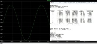
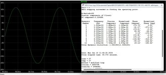
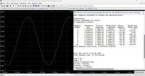
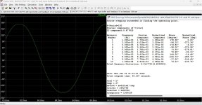
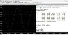
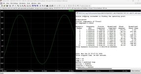
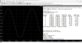
I did some simulations last evening comparing distortion and feedback levels.
I did some simulations last evening comparing distortion and feedback levels.
| Gain | Feedback | 1W 8R THD | 18W 8R THD | |
| No Feedback | 19.7dB | --- | 0.9% | 4.5% |
| Min Feedback | 8.0dB | 11.7dB | 0.4% | 2.7% |
| Max Feedback | 0.6dB | 19.1dB | 0.2% | 1.5% |
Attachments
-
 BAF2015 SIT Amp No feedback.jpg314.9 KB · Views: 169
 -
 BAF2015 SIT Amp No feedback 1W.jpg250.5 KB · Views: 146
 -
 BAF2015 SIT Amp No feedback 18W.jpg247.2 KB · Views: 111
 -
 BAF2015 SIT Amp Feedback 51k Input Min feedback.jpg344.7 KB · Views: 121
 -
 BAF2015 SIT Amp Feedback 51k Input Min feedback 1W.jpg254.2 KB · Views: 109
 -
 BAF2015 SIT Amp Feedback 51k Input Min feedback 18W.jpg245.7 KB · Views: 111
 -
 BAF2015 SIT Amp Feedback 51k Input Max feedback.jpg345.5 KB · Views: 118
 -
 BAF2015 SIT Amp Feedback 51k Input Max feedback 1W.jpg249.9 KB · Views: 115
 -
 BAF2015 SIT Amp Feedback 51k Input Max feedback 18W.jpg245.2 KB · Views: 151
Ben, I am perhaps missing the point of this exercise. What have you gained in comparison to a simple follower?
It's all the same amp, except for the amount of feedback. One version has no feedback, the second version has some feedback, and the third version has more feedback.
Not asking about the same amp. Comparing your new design to the old source follower. Both have nearly unity voltage gain. The nfb amp seems to perform objectively worse than the source follower, isn't it? In what way is the new amp an improvement?
Yes, it does perform worse if the distortion is the only criterion.
But there are other factors, some are intangible.
I build amplifiers for fun. It is a hobby for me, and this is part of the exploration and journey. I am building this to experience it, to hear it for myself.🙂
But there are other factors, some are intangible.
I build amplifiers for fun. It is a hobby for me, and this is part of the exploration and journey. I am building this to experience it, to hear it for myself.🙂
We’re in it for the journey not the destination. It has an interesting character. And the distortion is… tolerable.
But there are other factors, some are intangible.
Absolutely, cannot argue with this.
Rahul built a choke loaded Tokin common source amp with feedback, so similar except with choke load:
https://www.diyaudio.com/community/...et-tdv-amp-using-2sk2087c.388926/post-7554089
https://www.diyaudio.com/community/...et-tdv-amp-using-2sk2087c.388926/post-7554089
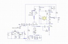
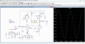
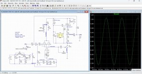
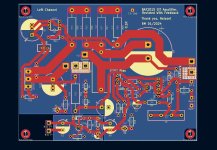
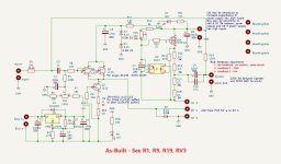
I've spent enough time staring at the left channel PCB design that it is time to order it. I always go for the cheap shipping so it will take about three weeks for them to get to me.
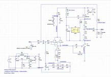
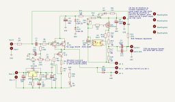
PCB is 100mmx130mm, mounting holes on a 90mmx120mm grid.
PCB is 100mmx130mm, mounting holes on a 90mmx120mm grid.
Attachments
-
 BAF2015 SIT Amp with Feedback Left Channel LTSpice.jpg197.1 KB · Views: 279
 -
 BAF2015 SIT Amp with Feedback Left Channel Schematic.jpg96.8 KB · Views: 272
 -
 BAF2015 SIT Amp with Feedback Left Channel PCB Copper.jpg141.8 KB · Views: 237
 -
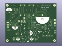 BAF2015 SIT Amp with Feedback Left Channel PCB.jpg101.9 KB · Views: 187
 -
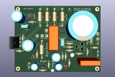 BAF2015 SIT Amp with Feedback Left Channel PCB stuffed.jpg108.6 KB · Views: 263
Looks good Ben,
I'm thinking about something running on a lower power supply as well. Maybe parallels 2sk82's with a current source. The 2SK82's like a VDS of 20v.
I'm very interested in what you think compared to your Choke loaded or MU loaded common drain followers.
Keep up the good work!
I'm thinking about something running on a lower power supply as well. Maybe parallels 2sk82's with a current source. The 2SK82's like a VDS of 20v.
I'm very interested in what you think compared to your Choke loaded or MU loaded common drain followers.
Keep up the good work!
It will probably sound a bit different since the distortion will be higher than with common drain followers. I will mount pin sockets at the feedback resistor location so that I can try different amounts of feedback. The question is will it end up sounding closer to common drain or no feedback common source? Or something decidedly in between?
But I have to build it first.
But I have to build it first.
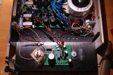
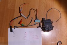
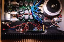
The left channel is almost ready for the first power-up.
The only part that needs to be installed is the source resistor for the J113 CCS at the input JFET buffer. Pin headers were installed to allow for quick and easy change of the resistor. There is also a 10 Ohm resistor installed that is part of the source resistance for current measurement.
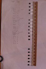
The J113 for the buffer and CCS were measured for Idss with a jig that I made. It is hardwired, with an old linear 12V 1A wall wart for power. The wall wart measured way over 12V unloaded so I added a 100 Ohm 5W bleed resistor and that brought the voltage down to a stable 11.4V. A ZIF socket accepts either clip leads for the J113 or the J113 directly.
To measure the Idss, I plugged the power supply plug into the jack, quickly noted the current, and then quickly unplugged the power. The current would start high, and then quickly decrease. So a quick decision had to be made as to what number I saw on the meter. Because of this, I would say that my measurements may have an error of +/-0.3mA. The Idss at 11.4V were all between 20 and 27mA. I bought 20 J113 and using my choice of matching within 0.5mA (due to possible error by me quickly reading the numbers correctly), there were many matching pairs and many of the pairs were close enough to be considered quads. Perhaps I got a really good batch and not all batches would be this close. Below is a picture of the Idss measurements. The measurements were also written in red ink on the paper strip but they did not show up in the picture.
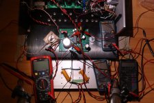
For the first power-up of the left channel, the THF-51S will not be connected. In its place my 8 Ohm amplifier test load will be installed in place of the THF-51S, connected to the THF-51S drain and source connection points in the amplifier circuit, to test the mosfet current source. Meters will monitor the JFET buffer current, output current source current, bias supply voltage, and voltage across the test load.
A dim bulb tester will be used for the first power-up, and if there is no excessive current draw, the bias voltage trimmer and output current source trimmer will be adjusted to check that they work as intended. If all goes well, the dim bulb tester will be removed and full AC power applied. If that goes well, the THF-51S will be installed and powered up with the dim bulb tester in place. If no issues, then unthrottled AC will be applied and trimmers adjusted for final operating voltages/currents.
First power-up will be tomorrow. Fingers crossed. 🤞
The only part that needs to be installed is the source resistor for the J113 CCS at the input JFET buffer. Pin headers were installed to allow for quick and easy change of the resistor. There is also a 10 Ohm resistor installed that is part of the source resistance for current measurement.
The J113 for the buffer and CCS were measured for Idss with a jig that I made. It is hardwired, with an old linear 12V 1A wall wart for power. The wall wart measured way over 12V unloaded so I added a 100 Ohm 5W bleed resistor and that brought the voltage down to a stable 11.4V. A ZIF socket accepts either clip leads for the J113 or the J113 directly.
To measure the Idss, I plugged the power supply plug into the jack, quickly noted the current, and then quickly unplugged the power. The current would start high, and then quickly decrease. So a quick decision had to be made as to what number I saw on the meter. Because of this, I would say that my measurements may have an error of +/-0.3mA. The Idss at 11.4V were all between 20 and 27mA. I bought 20 J113 and using my choice of matching within 0.5mA (due to possible error by me quickly reading the numbers correctly), there were many matching pairs and many of the pairs were close enough to be considered quads. Perhaps I got a really good batch and not all batches would be this close. Below is a picture of the Idss measurements. The measurements were also written in red ink on the paper strip but they did not show up in the picture.
For the first power-up of the left channel, the THF-51S will not be connected. In its place my 8 Ohm amplifier test load will be installed in place of the THF-51S, connected to the THF-51S drain and source connection points in the amplifier circuit, to test the mosfet current source. Meters will monitor the JFET buffer current, output current source current, bias supply voltage, and voltage across the test load.
A dim bulb tester will be used for the first power-up, and if there is no excessive current draw, the bias voltage trimmer and output current source trimmer will be adjusted to check that they work as intended. If all goes well, the dim bulb tester will be removed and full AC power applied. If that goes well, the THF-51S will be installed and powered up with the dim bulb tester in place. If no issues, then unthrottled AC will be applied and trimmers adjusted for final operating voltages/currents.
First power-up will be tomorrow. Fingers crossed. 🤞
Attachments
-
 BAF2015 THF-51S with Feedback- Left Channel.JPG401.9 KB · Views: 144
 -
 BAF2015 THF-51S with Feedback -Left Channel Board.JPG334.5 KB · Views: 133
 -
 BAF2015 THF-51S with Feedback-Left Channel Power-up Measurements.JPG373.3 KB · Views: 132
 -
 J113 Idss measurement.JPG297.5 KB · Views: 138
 -
 J113 Idss mA.JPG187.1 KB · Views: 139
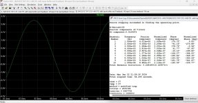
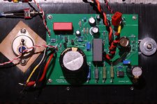
The left channel power-up was a success. It was done in stages as described in my previous post, with no surprises. I ended up with a 60 Ohm resistor at the JFET CCS source, in addition to the 10 Ohm resistor, for a total of 70 Ohm which resulted in 10.5mA of current.
To confirm that the amplifier was working properly, some FFT measurements were done. That was done with 2.0A Iq and 23.5V THF-51S Vds. This will most likely not be the final operating Iq and Vds, as the distortion was a bit higher than I like. More on this in a later post (hint: lower Iq and higher Vds).
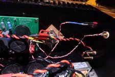
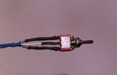
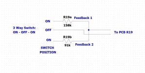
Since I had no idea what to expect with feedback added, I included a feedback selector switch so that no feedback, some feedback, and more feedback can be selected. In conjunction with a 25.5k resistor at the input, the lower level of feedback (feedback 1) has a 158k resistor at the amplifier output, and the higher level of feedback (feedback 2) has a 91k resistor at the amplifier output.
To confirm that the amplifier was working properly, some FFT measurements were done. That was done with 2.0A Iq and 23.5V THF-51S Vds. This will most likely not be the final operating Iq and Vds, as the distortion was a bit higher than I like. More on this in a later post (hint: lower Iq and higher Vds).
Since I had no idea what to expect with feedback added, I included a feedback selector switch so that no feedback, some feedback, and more feedback can be selected. In conjunction with a 25.5k resistor at the input, the lower level of feedback (feedback 1) has a 158k resistor at the amplifier output, and the higher level of feedback (feedback 2) has a 91k resistor at the amplifier output.
Attachments
-
 BAF2015 THF-51S with Feedback voltages.JPG383.8 KB · Views: 165
 -
 BAF2015 SIT Amp with Feedback - As-Built.jpg124.5 KB · Views: 165
 -
 BAF2015 THF-51S fdbk amp left channel.JPG379.2 KB · Views: 163
 -
 BAF2015 THF-51S with Feedback switch.JPG292.1 KB · Views: 113
 -
 BAF2015 THF-51S amp feedback select switch.JPG159.3 KB · Views: 120
 -
 Feedback select switch.jpg95.5 KB · Views: 105
 -
 BAF2015 THF-51S Fdbk amp back panelI.JPG280.4 KB · Views: 113
- Home
- Amplifiers
- Pass Labs
- BAF2015 Amplifier - A SIT Mu Follower, Revisited with Feedback