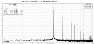
I am listening to the left channel right now. It is powering my right speaker and my THF-51S Mu Follower Follower is powering the left speaker. Since the Mu Follower Follower is common drain, with no voltage gain, and the BAF2015 THF-51S is common source with voltage gain, the Mu Follower has the ACP+ connected to it for voltage gain. The preamp is the DIY FE 2022. The 2SK79 preamp at the bottom of the preamp stack is not in use.
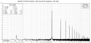
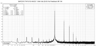
The BAF2015 THF-51S is set at no feedback right now. As can be seen in the picture, Iq is 1.64A and THF-51S Vds is 28V. More information to come.
Right now I am enjoying the sound. 🙂
The BAF2015 THF-51S is set at no feedback right now. As can be seen in the picture, Iq is 1.64A and THF-51S Vds is 28V. More information to come.
Right now I am enjoying the sound. 🙂
Attachments

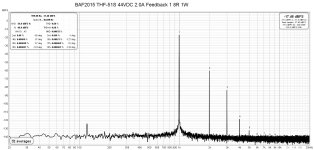
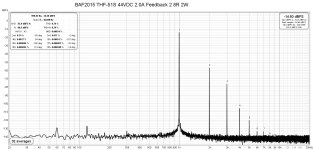
In my previous post I said that I had the feedback set at zero, but it was actually set at maximum. I switched it to no feedback but it was only for a short time as the ACP+ did not have enough gain to give the Mu Follower Follower amp enough voltage to match the BAF2015. I am now listening with the feedback set at the lower level. My ears and brain seem to hear a difference, with the higher distortion of no feedback having an effect on the midrange and higher frequencies. It is a type of "tone" control, I suppose. I have built in two levels of feedback but if more levels of feedback to choose from is desired, a rotary switch with many resistors could be employed, or for infinite adjustability a 50k or so resistor in series with an 1000k pot could be used instead.
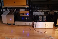
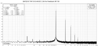
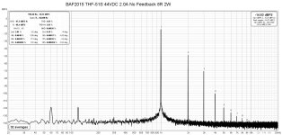
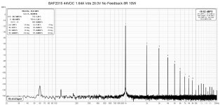
Below are the FFT plots done with the initial operating point of 2.0A and 23.5V Vds. The distortion was much higher than I anticipated based on LTSpice simulations. So I changed Iq and Vds and compared distortion profiles. I ended up with 1.64A Iq and 28V THF-52S Vds. The 1.64V Iq was as low as the circuit would go without changing resistors in the mosfet CCS. The 28V Vds was where the distortion was at what I thought was a reasonable level. The positive of this operating point was lower distortion but a negative was that the third harmonic became dominant at a lower output power level, and the maximum useable power output was lower.
Next on the to-do list is to determine the gain and feedback levels. After that I will run some more FFTs with the DIY FE 2022 after my 1kHz oscillator to provide more gain to obtain FFTs at higher amplifier output levels.
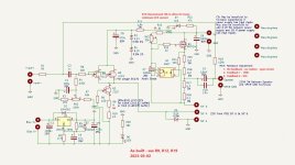
One change that I may make in the future is to change the values of R15 to R18. Currently there is 0.3 Ohm total between the speaker out and THF-51S drain and 0.4 Ohm total between the speaker out and the CCS mosfet source. This favours a bit more single ended action, resulting in a bit higher distortion and less power output. Adjusting the resistor values so that the resistance is equal on both sides of the speaker out should decrease distortion and increase power output. It probably will not be a big change, but it will be a good exercise.
Meanwhile, I am enjoying the music.
Below are the FFT plots done with the initial operating point of 2.0A and 23.5V Vds. The distortion was much higher than I anticipated based on LTSpice simulations. So I changed Iq and Vds and compared distortion profiles. I ended up with 1.64A Iq and 28V THF-52S Vds. The 1.64V Iq was as low as the circuit would go without changing resistors in the mosfet CCS. The 28V Vds was where the distortion was at what I thought was a reasonable level. The positive of this operating point was lower distortion but a negative was that the third harmonic became dominant at a lower output power level, and the maximum useable power output was lower.
Next on the to-do list is to determine the gain and feedback levels. After that I will run some more FFTs with the DIY FE 2022 after my 1kHz oscillator to provide more gain to obtain FFTs at higher amplifier output levels.
One change that I may make in the future is to change the values of R15 to R18. Currently there is 0.3 Ohm total between the speaker out and THF-51S drain and 0.4 Ohm total between the speaker out and the CCS mosfet source. This favours a bit more single ended action, resulting in a bit higher distortion and less power output. Adjusting the resistor values so that the resistance is equal on both sides of the speaker out should decrease distortion and increase power output. It probably will not be a big change, but it will be a good exercise.
Meanwhile, I am enjoying the music.
Attachments
-
 BAF2015 THF-51S 44VDC 2.0A No Feedback 8R 1W.jpg243.2 KB · Views: 99
 -
 BAF2015 THF-51S 44VDC 2.0A No Feedback 8R 2W.jpg244.7 KB · Views: 95
 -
 BAF2015 THF-51S 44VDC 2.0A No Feedback 8R 17W.jpg243.2 KB · Views: 95
 -
 BAF2015 THF-51S 44VDC 2.0A Feedback 1 8R 1W.jpg242.3 KB · Views: 80
 -
 BAF2015 THF-51S 44VDC 2.0A Feedback 2 8R 1W.jpg243 KB · Views: 96
 -
 BAF2015 THF-51S 44VDC 2.0A Feedback 2 8R 2W.jpg243.5 KB · Views: 96
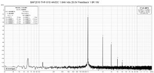
And here are the FFTs for 1.6A and 28V Vds:
Attachments
-
 BAF2015 THF-51S 44VDC 1.64A Vds 28.0 No Feedback 8R 1W.jpg246.1 KB · Views: 92
 -
 BAF2015 THF-51S 44VDC 1.64A Vds 28.0 No Feedback 8R 10W.jpg244.1 KB · Views: 86
 -
 BAF2015 THF-51S 44VDC 1.64A Vds 28.0 Feedback 1 8R 1W.jpg245.1 KB · Views: 81
 -
 BAF2015 THF-51S 44VDC 1.64A Vds 28.0 Feedback 1 8R 10W.jpg245 KB · Views: 85
 -
 BAF2015 THF-51S 44VDC 1.64A Vds 28.0 Feedback 2 8R 1W.jpg244.5 KB · Views: 89
Not to dampen your enthusiasm, but after extensive listening tests we dropped feedback in the SIT 4, so it's a Common Source gain stage without feedback biased by a mu follower, similar to the SIT 2.

Yes, I have seen that, but I had to try it and hear it for myself. That is also why I have included a switch to allow for no feedback, some feedback, and more feedback. It's a diy adventure! 🙂
Nelson, I’m curious about gain matching between channels. How do you do that without feedback? The parts appear to have some variation, at least in the tiny sample I have (4).Not to dampen your enthusiasm, but after extensive listening tests we dropped feedback in the SIT 4, so it's a Common Source gain stage without feedback biased by a mu follower, similar to the SIT 2.
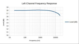
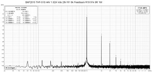
I have been listening to the left channel with feedback as the no feedback sound seemed deficient in the higher frequencies. There was no sparkle or clarity. So I checked the no feedback frequency response. I did it manually by inputting sine waves from a signal generator and monitoring the input and output voltages with an oscilloscope. The results showed a gradual decrease in output starting at about 5kHz. By 20kHz the output was about 1.6dB down.
With feedback I did not notice any deficiency in the higher frequencies during listening. But I made some changes to the circuit before I thought of measuring the frequency response with feedback. So I cannot confirm that the frequency response was better with feedback.
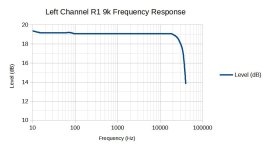
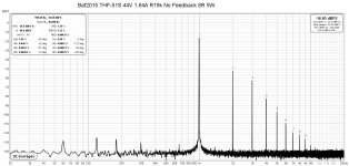
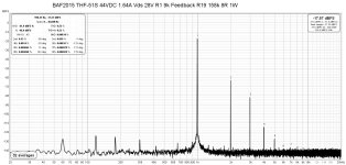
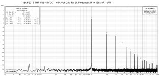
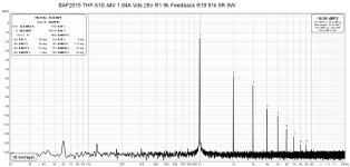
So remembering that Zen Mod had written that the resistor at the input affects the high frequencies, I ended up reducing R1 from 25.5k to 9k. That did the trick. Now the sound with no feedback no longer sounded deficient at high frequencies. I did not reduce the values of the feedback resistors at the speaker output. So effectively the amount of feedback was also reduced.
Measuring the gain:
-no feedback = 9.1X = 19.2dB gain
-feedback 1 = 5.8X = 15.3dB gain, 3.9dB feedback
-feedback 2 = 4.6X = 13.3dB gain, 5.9dB feedback
With this change, the no feedback sound is now quite good. During a short listening session I was not sure that I could tell the difference between the feedback and no feedback sound. However since I only have one channel built, I am listening to a combination of this amp in one channel and my 2SK79 preamp/THF-51S mu follower follower in the other channel.
Meanwhile I will spend time listening with feedback for a while, and then switch to no feedback to see whether I can hear a difference. A fairer listening evaluation will have to wait until the right channel is built. Hopefully that will be in two weeks or so as the right channel pcb has been fabricated and is awaiting shipment.
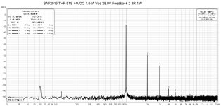
Below are the before and after frequency response graphs. Unfortunately I did not think to do the first test beyond 20kHz. Also below are the FFTs for the circuit with R1 = 9k.
With feedback I did not notice any deficiency in the higher frequencies during listening. But I made some changes to the circuit before I thought of measuring the frequency response with feedback. So I cannot confirm that the frequency response was better with feedback.
So remembering that Zen Mod had written that the resistor at the input affects the high frequencies, I ended up reducing R1 from 25.5k to 9k. That did the trick. Now the sound with no feedback no longer sounded deficient at high frequencies. I did not reduce the values of the feedback resistors at the speaker output. So effectively the amount of feedback was also reduced.
Measuring the gain:
-no feedback = 9.1X = 19.2dB gain
-feedback 1 = 5.8X = 15.3dB gain, 3.9dB feedback
-feedback 2 = 4.6X = 13.3dB gain, 5.9dB feedback
With this change, the no feedback sound is now quite good. During a short listening session I was not sure that I could tell the difference between the feedback and no feedback sound. However since I only have one channel built, I am listening to a combination of this amp in one channel and my 2SK79 preamp/THF-51S mu follower follower in the other channel.
Meanwhile I will spend time listening with feedback for a while, and then switch to no feedback to see whether I can hear a difference. A fairer listening evaluation will have to wait until the right channel is built. Hopefully that will be in two weeks or so as the right channel pcb has been fabricated and is awaiting shipment.
Below are the before and after frequency response graphs. Unfortunately I did not think to do the first test beyond 20kHz. Also below are the FFTs for the circuit with R1 = 9k.
Attachments
-
 BAF2015 THF-51s left channel freq resp 25.5k R1.jpg40.8 KB · Views: 89
 -
 Left Channel Frequency Response 9k R1.jpg36.1 KB · Views: 105
 -
 BAF2015 THF-51S 44VDC 1.64A Vds 28.0 R1 9k No Feedback 8R 1W.jpg247 KB · Views: 101
 -
 BAF2015 THF-51S 44VDC 1.64A Vds 28.0 R1 9k No Feedback 8R 5W.jpg244.6 KB · Views: 91
 -
 BAF2015 THF-51S 44VDC 1.64A Vds 28.0 R1 9k No Feedback 8R 10W.jpg247 KB · Views: 86
 -
 BAF2015 THF-51S 44VDC 1.64A Vds 28.0 R1 9k Feedback R19 158k 8R 1W.jpg247.8 KB · Views: 91
 -
 BAF2015 THF-51S 44VDC 1.64A Vds 28.0 R1 9k Feedback R19 158k 8R 5W.jpg246.1 KB · Views: 82
 -
 BAF2015 THF-51S 44VDC 1.64A Vds 28.0 R1 9k Feedback R19 158k 8R 10W.jpg247.7 KB · Views: 84
 -
 BAF2015 THF-51S 44VDC 1.64A Vds 28.0 R1 9k Feedback R19 91k 8R 1W.jpg246.9 KB · Views: 85
 -
 BAF2015 THF-51S 44VDC 1.64A Vds 28.0 R1 9k Feedback R19 91k 8R 5W.jpg246.2 KB · Views: 87
 -
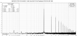 BAF2015 THF-51S 44VDC 1.64A Vds 28.0 R1 9k Feedback R19 91k 8R 10W.jpg247.4 KB · Views: 92
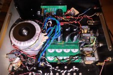
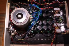
Some progress have been made on the right channel. The heat sink has been drilled and tapped and the right channel amplifier PCB has arrived.
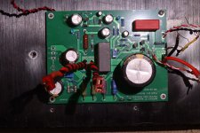
The power supply has also been cleaned up. As previously mentioned I am reusing the existing bipolar supply, since I do not anticipate needing the supply for a future amplifier. However I was not happy with the PS board that was in place. It was a board that I purchased from an Ebay merchant back when I knew much less about PS noise abatement. So I designed my own simple but effective PS board and moved the supply components onto the new board.
If I did not have the existing bipolar supply to reuse, I would have built an unipolar supply with 50V capacitors and a choke on the positive rail. So the reused supply saved me purchasing new capacitors but the downside is that it uses an extra choke. But it is money that was already spent. 🙂
Attachments

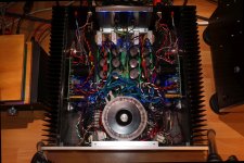
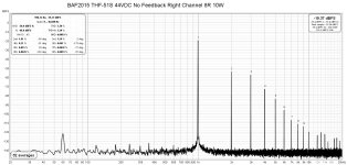
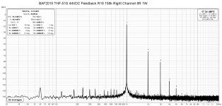
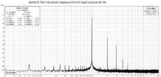
The right channel is finished and tested, and I have been listening to it for a few days now.
The right channel build went smoothly and powered up with no problems. FFTs show distortion levels very similar to the left channel's levels.
There was a difference in noise though as the right channel showed quite a bit of what I suppose was intermodulation distortion of the power supply noise and its harmonics. I spent a few hours trying to get to the bottom of this. Rotating the power transformers did not make a difference. Using the left channel power supply lessened the noise but did not get rid of it. All of the wires were already tightly twisted and moving the wires around did not make any appreciable difference. The only thing that worked was to provide some distance between the audio board and the power supply. So in the end I accepted the noise as although the noise was visible on the FFT plots, I did not hear any noise out of my 103dB speakers.
My use of an existing bipolar power supply for a single voltage most likely contributed to the noise. This effective halves the capacitance of the power supply as the negative and positive capacitors are in series. With 22mF capacitors, a pair in series becomes 11mF. That is quite a hit. However as I mentioned previously I have these parts so I reused them. Also, although it is a CLC supply, the choke is a Hammond 156B with only 1.5mH and a DCR of 0.07 Ohm. My other single ended amps have Hammond 159ZJ chokes which are 10mH and 0.16 Ohm, for much lower power supply ripple.
If didn't have the parts I would have built a proper unipolar power supply, with half the parts yet lower noise.
After a few days of listening, I quite like this amplifier. Although it is relatively low powered, it is more than enough for my speakers. Since the amplifier has gain, the ACP+ with only 9dB (2.8x) gain is more than enough as as preamp. I have tried no feedback and feedback and I like them all. The no feedback distortion level didn't seem to intrude much into music. I might have a slight preference for feedback though. It is probably system dependent and then still a personal preference. All in all, it has the VFET/SIT sound.
Attachments
-
 BAF2015 Tokin THF-51S Right Channel board near completion.JPG559.8 KB · Views: 128
 -
 BAF2015 Tokin THF-51S with Feedback Inrerior.jpg402.7 KB · Views: 134
 -
 BAF2015 Tokin THF-51S Amplifier Interior right channel .JPG467.6 KB · Views: 196
 -
 BAF2015 SIT Amp with Feedback - As-Built R2.jpg119.8 KB · Views: 217
 -
 BAF2015 THF-51S ACP+.JPG212.3 KB · Views: 188
 -
 BAF2015 THF-51S 44VDC Right Channel No feedback 8R 1W.jpg248.8 KB · Views: 120
 -
 BAF2015 THF-51S 44VDC Right Channel No feedback 8R 5W.jpg245.8 KB · Views: 111
 -
 BAF2015 THF-51S 44VDC Right Channel No feedback 8R 10W.jpg246 KB · Views: 108
 -
 BAF2015 THF-51S 44VDC Right Channel FeedbackR19 158k 8R 1W.jpg248 KB · Views: 112
 -
 BAF2015 THF-51S 44VDC Right Channel Feedback R19 91k 8R 1W.jpg247.1 KB · Views: 127

Glad you are enjoying it. Does the soundstage open wider than with the followers? It all depends on operating points and levels, but I am curious.
I did a listening comparison this morning between this amp and the much lower distortion high powered (62VDC 2.5A) THF-51S Mu-follower follower. So both are mu-followers, one common source and the other common drain. The power differential may or may not be a factor considering that the speakers are very sensitive. Speakers were connected for negative phase second harmonic distortion. Levels were set by ear so it wasn't very scientific. Also not scientific was that these are just my impressions. No measuring instruments were involved, assuming soundstage width can be measured. Can it?
In my opinion both amplifiers floated a very solid image that was detached from the speakers. That is probably also system dependent. As for soundstage width, my system is set up asymmetrically in the room with the left speaker about three feet from a window wall and the right speaker next to open space. With both amplifiers there seemed to be a sense of more sound coming from left of the speaker than from the right of the speaker. The centre image was still centred. My thought is that soundstage width may be strongly aided by sidewall reflections. When a side wall is close by, first reflections present a virtual image that appears to originate from a point outside of the speaker. Hence, the soundstage seemed wider to the left in my system.
Usually I don't think much about this. My usual approach is to listen and if the sound and music as a whole puts a smile on face, I am happy! 🙂
That is not an easy question to answer. The sound is very similar. It seems that regardless of which of my amplifiers I have in the system I enjoy the sound. I have several SIT amplifiers, and each is different in various ways. I enjoy listening to all of them and I rotate them in according to the season, as one of their differences is their power dissipation. The high dissipation amplifiers are enjoyed during the colder seasons and the low dissipation amplifiers are enjoyed during the warmer seasons.
When I switched my original high powered BAF2015 THF-51S from mu-follower to mu-follower follower, there was a noticeable difference in the high frequencies. There seemed to be more clarity, which made the music seem more real. However, this lower power version does not seem to lack in the high end compared to the mu-follower follower. It does have a much different operating point than the original BAF2015 amp, plus it has an input buffer whereas the original did not. These could be reasons but I am only guessing.
What ever differences in sound there may be between this mu-follower amp and the higher power mu-follower follower amp, they do not immediately jump out at me. Perhaps if my speakers need the extra power then there might be a more noticeable difference. Another factor may be that I am not the type of listener who obsesses over picky audiophile sound characteristics, nitpicking over small details and differences. The last sentence in my previous post says it all. 🙂
it has an input buffer whereas the original did not. These could be reasons but I am only guessing.
mostly that
Trying to find a design that works with my existing PSUs. Meaning one standard FW psu, and one F2J PSU. Otherwise I need to up the game voltage-wise.
I am still listening to and enjoying this amplifier. Yesterday while listening to Bob Marley's Exodus album, during Jammin' I heard an instrument appear distinctly left of the left speaker. I could not identify the sound. It was percussive in nature, longer in duration than a drum beat and much higher in frequency, but not as high in frequency as a triangle and the decay was shorter. Perhaps it was a synthesized tone. But what caught my attention was that it stood out, and was heard distinctly to emanate from a point outside of the speaker. The perceived source location fitted with the laws of reflection of waves, whether it be light or sound.

So some reflection in the listening room is good. 🙂
So some reflection in the listening room is good. 🙂
- Home
- Amplifiers
- Pass Labs
- BAF2015 Amplifier - A SIT Mu Follower, Revisited with Feedback