Friends here, everyone is particularly excited
Your development, especially fast
I see your enthusiasm
Your development, especially fast
I see your enthusiasm
as August said ...
speaking of one channel :
100R trimpots are for buffers , initially upper one (on schematic) set to 0 , confirmed with ohmmeter across R5 , while lower one set to max , confirmed with ohmmeter across R4
2K (1K for Babelfish M25) is for Iq , initially set to 0 , confirmed with ohmmeter , whichever way you find most adequate
10K (or 20K , as sent in last shipments) is for output DC offset , pretty much irrelevant initial setting
I'm finding easiest pre-set of trimpots is while pcbs still aren't mounted on heatsinks
physical position of trimpots on pcb ( screw where arrow on pcb or rotated for 180deg) is pretty much non-important ..... I'm anyway lousy at planning and remembering that orientation thing , always looking at multimeters to decide in which direction to turn them
dunno , most probably years of service work ...... it's easier and faster this way

yup, needle-ends
these I'm finding perfect as wire ends , for soldering on pcb
from now going to use them for amps , 2mm dia hole pad and Pressfit needle-ends of 2.5sqmm
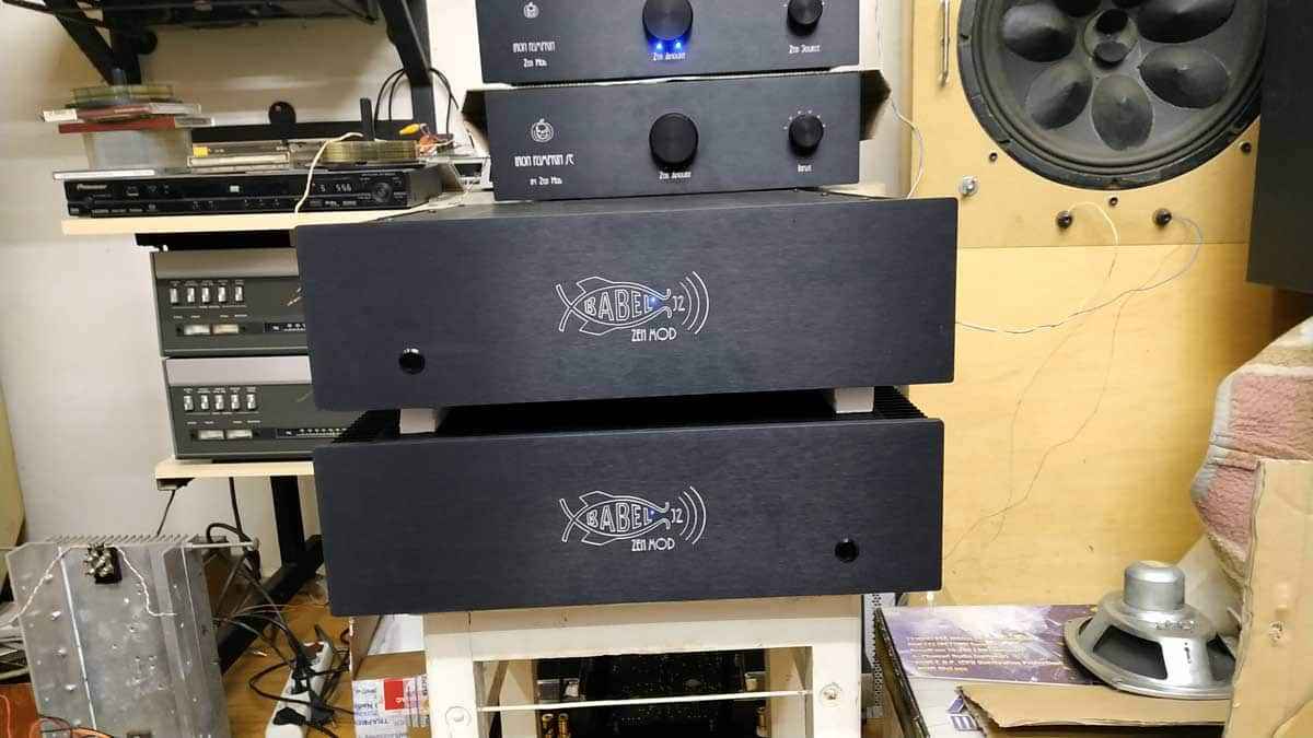
in fact , already used them , in Babelfish J2 monoblocks , I finished few weeks ago
these I'm finding perfect as wire ends , for soldering on pcb
from now going to use them for amps , 2mm dia hole pad and Pressfit needle-ends of 2.5sqmm
in fact , already used them , in Babelfish J2 monoblocks , I finished few weeks ago
Nice idea, will think about this!
There is a mistake in the pics .... if you changed the location of the switch then please flip (I mean mirror) also the logo.

I saw J2 .... some hints / breadcrumbs or pics (of course from inside)?
There is a mistake in the pics .... if you changed the location of the switch then please flip (I mean mirror) also the logo.
I saw J2 .... some hints / breadcrumbs or pics (of course from inside)?
Last edited:
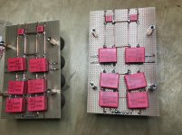
My PSUs are almost ready now as well ... 🙂
(Have some Motor Run Caps on order, to be placed at the back of the amp, and to have the Fastons from the PSUs connected to. From there to the amp boards then ...)
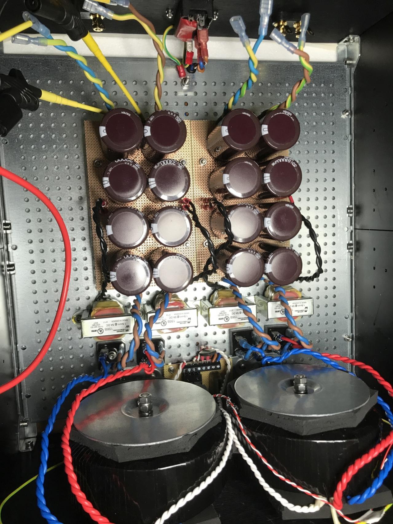
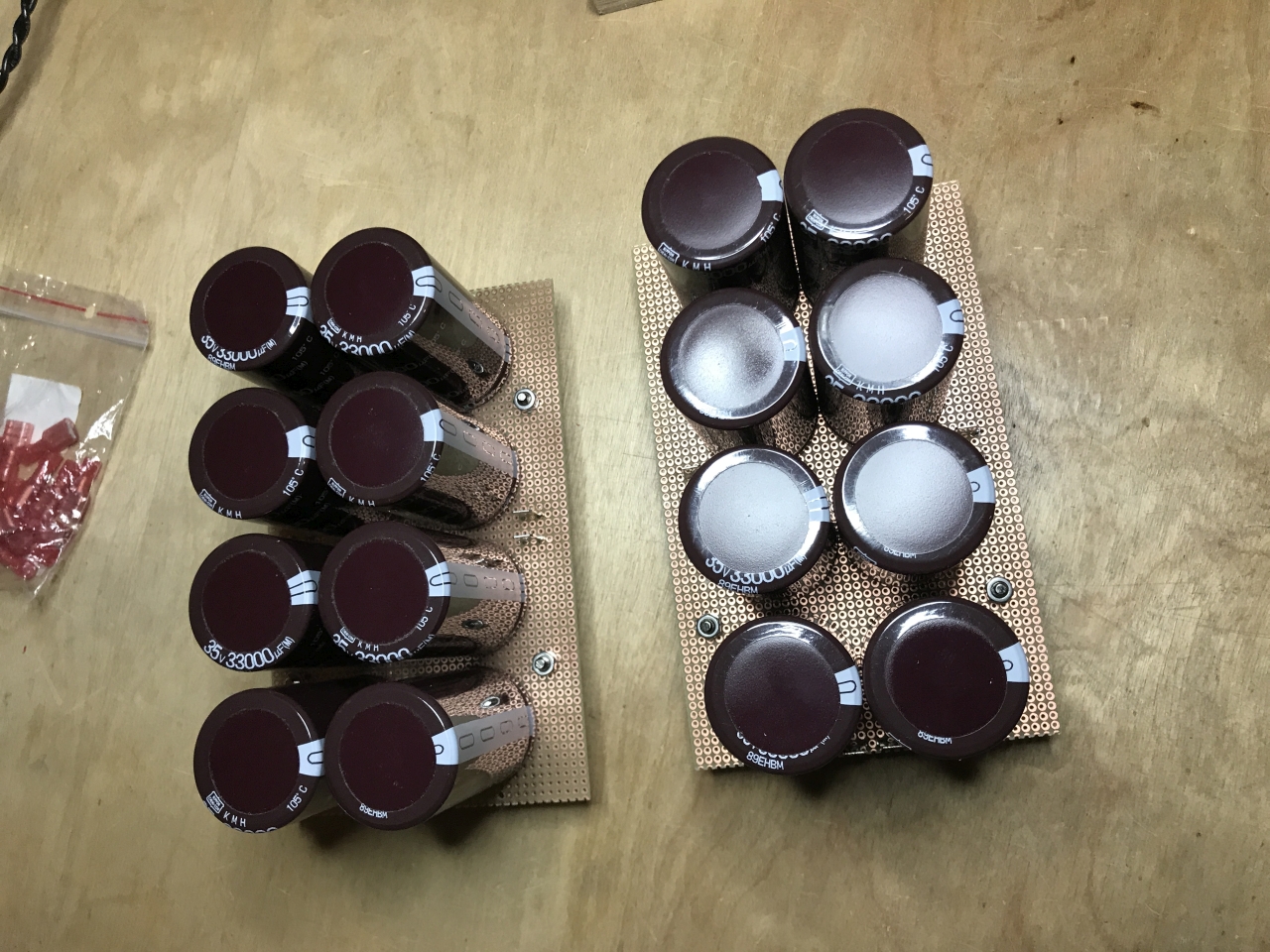
2.5 mm^2 wires soldered directly to the solidcore wire on the underside of the PSU boards. Bleeder resistors and some film caps also soldered from underneath. 😉

Have started stuffing the amp boards, but waiting for some more parts from Mouser and Reichelt ... 😛
Best regards,
Claas
(Have some Motor Run Caps on order, to be placed at the back of the amp, and to have the Fastons from the PSUs connected to. From there to the amp boards then ...)
2.5 mm^2 wires soldered directly to the solidcore wire on the underside of the PSU boards. Bleeder resistors and some film caps also soldered from underneath. 😉
Have started stuffing the amp boards, but waiting for some more parts from Mouser and Reichelt ... 😛
Best regards,
Claas
Attachments

if you're going to put motorruns , all those wimas are unnecessary
how's Diyaudio pre-drilled heatsink against my pcbs?
how's Diyaudio pre-drilled heatsink against my pcbs?
I have a place on one of my boards, I thought it was a deformed solder pad, but under magnification it looks like some of the blue mask has come off or is missing?
For some reason, I cant seem to upload pics...never been a problem before, I keep getting the "Aww snap" thing. Tried rebooting, incognito page, original settings etc. but no help..
I will when I can. Is the missing mask a problem?
Russellc
For some reason, I cant seem to upload pics...never been a problem before, I keep getting the "Aww snap" thing. Tried rebooting, incognito page, original settings etc. but no help..
I will when I can. Is the missing mask a problem?
Russellc
I cant post pics on any forum, something wrong with my settings. I will try another browser. Anybody know any pic posting tricks?
Russellc
Russellc
![IMG_4712[1].JPG](/community/data/attachments/674/674141-6d4cb9c485300d52921e034f93bbee3c.jpg?hash=bUy5xIUwDV)
zen mod has the final say but I wouldn't expect that to have any impact ..dB
At first I wondered, as continuity showed across the "bald" part....but so do the small pads on the unaffected board.
You are right, will wait for ZM's final say.
Russellc
nothing to worry about, that's just solder mask cooked while soldering little buggers with hot air
all jfets checked for continuity of contacts , cleaned with alcohol afterwards , even if using no-clean flux
all jfets checked for continuity of contacts , cleaned with alcohol afterwards , even if using no-clean flux
if you're going to put motorruns , all those wimas are unnecessary
Yeah ... that was just my usual modular thinking to have the PSUs as building blocks that could be re-used by themselves ... 😛
how's Diyaudio pre-drilled heatsink against my pcbs?
Haven't tried yet ... boards are still in their frame. Once I'm finished stuffing them, I will remove the heatsink from the case, deburr and smooth the output transistors' mounting area, and drill & tap one more hole for the THF-51S. Then I will be able to report ... 😀
Best regards, Claas
- Home
- Amplifiers
- Pass Labs
- Babelfish M25, SissySIT - general building tips and tricks