How to make your SissySIT less sissy ....... or just hope to make it 🙂 -6N139 Opto
OK
few words again .......
- nothing wrong really with original Optocoupler arrangement ; if gates in OS are normal and nicely behaved ( no gate leakage) , entire Shebang is behaving as any Papamp sans NFB , relying on stability ( both Iq and DC Offset wise) in thermal equilibrium condition ; even if there is obvious Iq governing mech. tasks are too tricky and result is very carefully chosen set of compromises ....... go figure
(wanna few words more - read this in bracket , if not - jump further .... biasing mechanismus can be made stiffer , but with price of substantially decreasing Rin of input stage , being mush tougher for input stage ; price - decreased speed , lowered highs ...... of course , there are other ways of biasing , but this was idea at a time ...... and pursuing other ways if just an idea for now)
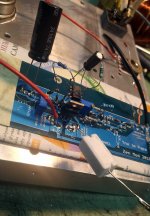
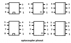
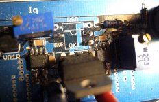
so , for starters , just few pics from developing phase of biasing with Darlington Opto , and important reference - how to read pin 1
OK
few words again .......
- nothing wrong really with original Optocoupler arrangement ; if gates in OS are normal and nicely behaved ( no gate leakage) , entire Shebang is behaving as any Papamp sans NFB , relying on stability ( both Iq and DC Offset wise) in thermal equilibrium condition ; even if there is obvious Iq governing mech. tasks are too tricky and result is very carefully chosen set of compromises ....... go figure
(wanna few words more - read this in bracket , if not - jump further .... biasing mechanismus can be made stiffer , but with price of substantially decreasing Rin of input stage , being mush tougher for input stage ; price - decreased speed , lowered highs ...... of course , there are other ways of biasing , but this was idea at a time ...... and pursuing other ways if just an idea for now)
so , for starters , just few pics from developing phase of biasing with Darlington Opto , and important reference - how to read pin 1
Attachments
Last edited:
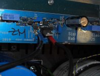
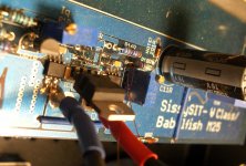
Let start with right channel , as written on pcb
cutting pliers - cut opto pins close to body, toss opto to bin , R15 - cut pins close to body , toss it
de-solder redundant pins from pcb and remove them with tweezers
add little solder on each pad - easier to manage later
cutting pliers - cut opto pins close to body, toss opto to bin , R15 - cut pins close to body , toss it
de-solder redundant pins from pcb and remove them with tweezers
add little solder on each pad - easier to manage later
Attachments

Last edited:
....
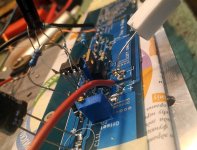
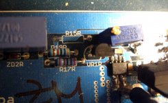
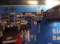
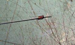
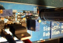
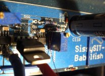
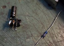
time to deal with R18 - we need to lift left pin - closer to opto , and to insert additional 1N4148 diode
considering space and approach only from top , for me was easiest to use thin (0.2mm) CuL wire as hook , to pull pin while heating with solder ; again add some solder to pad
when you're done , prepare 1N4148 ( observe where Cathode stripe goes), gently heat solder on pad , push diode pin in hole ; if needed , redo solder point to look fine
tie and solder free ends of 1N4148 and R18 , leave one end long
Attachments
-
 CIMG0030.jpg81.1 KB · Views: 143
 -
 CIMG0029.jpg61 KB · Views: 129
 -
 CIMG0028.jpg74.4 KB · Views: 131
 -
 CIMG0027.jpg70.3 KB · Views: 140
 -
 CIMG0026.jpg87.7 KB · Views: 139
 -
 CIMG0025.jpg87.2 KB · Views: 128
 -
 CIMG0024.jpg91.3 KB · Views: 135
 -
 CIMG0023.jpg98 KB · Views: 141
 -
 CIMG0022.jpg96.8 KB · Views: 162
Last edited:
........
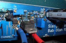
prepare 100R MF - bend legs and cut them short , solder them in R15 position
easiest to heat pad and push pin in hole , same for both pins ; redo to look fine
now you already have some leftover wire from resistor and diode pins - take 4 pcs (from trash if needed ) and solder them as Mustaches in all 4 opto pads
20mm will do , we will trim them later
prepare 100R MF - bend legs and cut them short , solder them in R15 position
easiest to heat pad and push pin in hole , same for both pins ; redo to look fine
now you already have some leftover wire from resistor and diode pins - take 4 pcs (from trash if needed
) and solder them as Mustaches in all 4 opto pads20mm will do , we will trim them later
Attachments

Last edited:
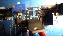
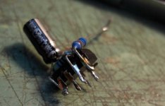
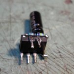
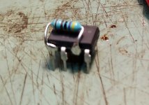
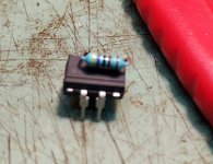
6N139 preparing
cut pins 1 and 4
observe trice , cut once
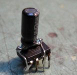
take 4K7 MF resistor ( even tiniest size will do) and 10uF elco (even 6V3 will do , but normal is 16V)
form resistor legs as per pics and solder to pins 5 and 7 on opto
solder elco on top of resistor , positive to pin 7 ( not!! like I got it on pics )
take 5K6 MF resistor ( even tiniest size will do ) and solder to pin 8 - do not bend it as on pic , leave it pointing up and bend it later where needs to be bent
cut pins 1 and 4
observe trice , cut once
take 4K7 MF resistor ( even tiniest size will do) and 10uF elco (even 6V3 will do , but normal is 16V)
form resistor legs as per pics and solder to pins 5 and 7 on opto
solder elco on top of resistor , positive to pin 7 ( not!! like I got it on pics
)take 5K6 MF resistor ( even tiniest size will do ) and solder to pin 8 - do not bend it as on pic , leave it pointing up and bend it later where needs to be bent
Attachments

Last edited:
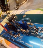
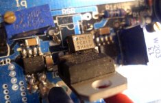
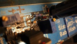
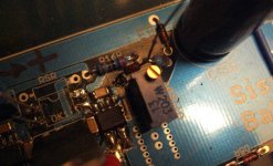
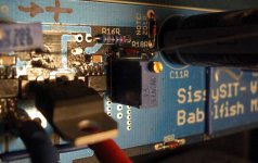
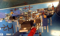
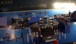
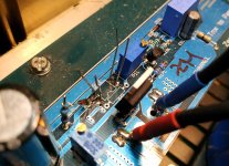
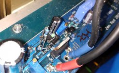
now , with tweezers , put entire thingie for mock-up between Moustaches on pcb , approx 5mm above pcb itself ; bend 7805 slightly away , to make more place
pin 2 of 6N139 goes in place of pin 1 of PC817
pin 3 of 6N139 goes in place of pin 2 of PC817
pin 6 of 6N139 goes in place of pin 3 of PC817
pin 7 of 6N139 goes in place of pin 4 of PC817
when you got it - if needed bend slightly each Moustach to accommodate - solder 6N in place and trim Moustaches
bend adequately remaining free resistor ( 5K6) , join with R18+Diode joining point , solder together , cut leftover leg
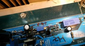
few pics as illustration , ignore that they're of Left Channel pcb ; difference to right one is that R15 and R18 are on opposite sides
ignore additional resistor soldered between pins 5 & 6 of 6N - my own Sissy is extremely tricky - Ugs window between SIT and MOS being just 720mV or so ........ I really didn't need to tweak it from original opto , but it is beneficiary for Greedy Boyz and also for learning sake
pin 2 of 6N139 goes in place of pin 1 of PC817
pin 3 of 6N139 goes in place of pin 2 of PC817
pin 6 of 6N139 goes in place of pin 3 of PC817
pin 7 of 6N139 goes in place of pin 4 of PC817
when you got it - if needed bend slightly each Moustach to accommodate - solder 6N in place and trim Moustaches
bend adequately remaining free resistor ( 5K6) , join with R18+Diode joining point , solder together , cut leftover leg
few pics as illustration , ignore that they're of Left Channel pcb ; difference to right one is that R15 and R18 are on opposite sides
ignore additional resistor soldered between pins 5 & 6 of 6N - my own Sissy is extremely tricky - Ugs window between SIT and MOS being just 720mV or so ........ I really didn't need to tweak it from original opto , but it is beneficiary for Greedy Boyz and also for learning sake
Attachments
......
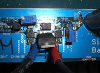
repeat everything with second channel ; again - difference being just R15 and R18 being on opposite sides
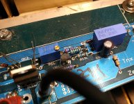
turn both (channels) Iq trimpots all the way CCW (shown on pics) , to set Iq to min for start
go back in thread ( first page , I believe ) , re-do biasing and DC offset setting procedure , preferably one channel at a time
again .......... :
- if you're starting from scratch - only you can decide will you go with original CNY17 optos , or right away with 6N139
- I can't guarantee that this remedy will cure all problematic SIT specimens; more AL involved in heatsinking , problem is smaller , that's simple physics ..... and - no matter how cute SIT is looking and how much we want it flawlessly operative and how much we hate even though of replacing it , when gate is leaking too much , it's leaking too much
if I forgot something , shoot
and - as always - blame Papa

repeat everything with second channel ; again - difference being just R15 and R18 being on opposite sides
turn both (channels) Iq trimpots all the way CCW (shown on pics) , to set Iq to min for start
go back in thread ( first page , I believe ) , re-do biasing and DC offset setting procedure , preferably one channel at a time
again .......... :
- if you're starting from scratch - only you can decide will you go with original CNY17 optos , or right away with 6N139
- I can't guarantee that this remedy will cure all problematic SIT specimens; more AL involved in heatsinking , problem is smaller , that's simple physics ..... and - no matter how cute SIT is looking and how much we want it flawlessly operative and how much we hate even though of replacing it , when gate is leaking too much , it's leaking too much
if I forgot something , shoot
and - as always - blame Papa
Is there a way for everyday dummy to measure this gate leakage? My specimens came from Pras, dont know if this was measured parameter at time or not.
If measurable by myself, what figure is good or bad?

thanks,
Russellc
it's easy - make that funny matching setup, I posted sketch of, earlier in the thread ....... and measure voltage across gate resistor
but - Catch 22 - what value will show and guarantee sliding nature of it , I'm still young to decide
maybe some of Giants could chime in , if they have some free time , left of walks by Shore , observing Whales , and making new toyz for Greedy Boyz Store
just build it ......... and you'll most probably find yourself lucky ........
in worstworstworst case , you'll end up with Babelfish M25 , which is (we all know) Berserking version of already Best Amp Around
does it make BAAB ?
Impatient
I'm working my way through this thread from start to finish. Almost seems like it is growing as fast as I read.🙁
Anyway, I would really like to get the Babelfish M25/Sissy Sit boards and The most complete kit for the M25 build that I can. How do I do that?
Probably here somewhere but there is a lot to read (and learn).
Thanks in advance.
Don
Very nice Zen Mod, the eagle eye photos look good. I think I’ll try and tighten up the devices by using SMD’s.
What does decreased speed , lowered highs effect?
My sissy rises 120ma over 5 hours as it reaches its thermal equilibrium. With more grip from different opto circuit what is predicted behaviour?
(biasing mechanisms can be made stiffer , but with price of substantially decreasing Rin of input stage , being mush tougher for input stage ; price - decreased speed , lowered highs ...... of course , there are other ways of biasing , but this was idea at a time ...... and pursuing other ways if just an idea for now)
What does decreased speed , lowered highs effect?
My sissy rises 120ma over 5 hours as it reaches its thermal equilibrium. With more grip from different opto circuit what is predicted behaviour?
I'm working my way through this thread from start to finish. Almost seems like it is growing as fast as I read.🙁
Anyway, I would really like to get the Babelfish M25/Sissy Sit boards and The most complete kit for the M25 build that I can. How do I do that?
Probably here somewhere but there is a lot to read (and learn).
Thanks in advance.
Don
Here you go:
SissySIT - kit packages
and this:
Babelfish M25 , AKA M2 on steroids , AKA M2-XA25 bstrd - kit packages
Last edited:
Very nice Zen Mod, the eagle eye photos look good. I think I’ll try and tighten up the devices by using SMD’s.
What does decreased speed , lowered highs effect?
My sissy rises 120ma over 5 hours as it reaches its thermal equilibrium. With more grip from different opto circuit what is predicted behaviour?
120mA/5Hrs ...... just chill Bro
just re-check it in Summer , then forget
decreased speed , lowered highs = slower rise times/slower amp generally , more db shaven off at 20KHz .......... polite and boring sound , so you could ask your self - why I did bother ?......
Last edited:
decreased speed , lowered highs = slower rise times/slower amp generally , more db shaven off at 20KHz .......... polite and boring sound , so you could ask your self - why I did bother ?......
Hmm, this makes me doubt that do I really want to so this mod.
Any ideas where to get small and accurate Vdc-display to permanent install? 😀
time gap
Hopefully there is a way to do this with the time gap involved. ZenMod is being pulled in a lot of directions right now. I have no idea how he does it all. Helps to be good at it though.🙂
Thanks for your direction.
Don
Hopefully there is a way to do this with the time gap involved. ZenMod is being pulled in a lot of directions right now. I have no idea how he does it all. Helps to be good at it though.🙂
Thanks for your direction.
Don
Hmm, this makes me doubt that do I really want to so this mod.
Any ideas where to get small and accurate Vdc-display to permanent install? 😀
Yes, it looks like a solution to misbehaving SIT, and if the offset is halved +\- 60ma during 5hr thermal variation there’s no real sacrifice.
A vdc will just cause you a headache and take away from audio bliss.
I’m dodo, but the idea of using a device that would increase resistance slightly when above 50*C to lower bias might be an option.....
A temperature coefficient device for increasing resistance to infinity at 50*C and a small resistor to limit voltage when Device is cold, basically bring the bias up faster.
Last edited:
A vdc will just cause you a headache and take away from audio bliss.
I’m actually considering this, it seems that my SITs behave differently every day. So, would like to do some longer period measuring to deicide mod or not to mod 🙂
Lol, mine could be a distant cousin to yours then.I’m actually considering this, it seems that my SITs behave differently every day. So, would like to do some longer period measuring to deicide mod or not to mod 🙂
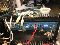
First channel is cooking in temporary case. No mod done to the original opto and seem to be pretty stable at 1.5A iq. Offset is moving +/- 15mv from 0. Heat sink is at 45c SITs are 2sk182 from pras
I will probably not run it at 1.8A since my heat sinks are not that big. Is there a lower limit to the bias for the circuit to perform normally?
Hubert
I will probably not run it at 1.8A since my heat sinks are not that big. Is there a lower limit to the bias for the circuit to perform normally?
Hubert
Attachments
- Home
- Amplifiers
- Pass Labs
- Babelfish M25, SissySIT - general building tips and tricks