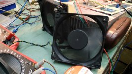
to make things faster while testing ..... I did use Vents to cool down the heatsink and I did use Heat Gun to warm it up 
see pic of screamers in action 🙂
see pic of screamers in action 🙂
Attachments


Very nice Zen Mod. Thanks for sharing all the different schematics and photos. I like to watch the pro’s at work....
Is this mod something that is required, or just for those amps that drift? It does not look like a clean modification.
it'll be clean modification , two additional resistors and cap sitting at new opto
however , if your Sissy is stable enough for your liking , no worries - you're blessed with well behaving SITs
however , if your Sissy is stable enough for your liking , no worries - you're blessed with well behaving SITs
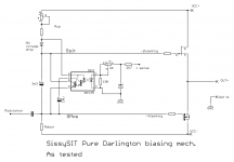
and , first next day I manage to find some time , I'm going to try Beastie approach , just to see how stable I can make it ...... pure darlington with zillion gain
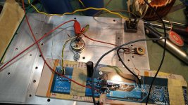
so , I did found some time today
see attached
behavior in temp equilibrium :
mains/rails -10% : DC offset +175mV, Iq 1A6
mains/rails nominal : DC offset +5mV, Iq 1A8
mains/rails +10% : DC offset -170mV , Iq 2A0
cold start : DC offset 65mV , Iq 2A05
conclusion - I'm staying with solution from post #1500 ; cold start is pretty much the same , while changes due to mains fluctuation are somewhat lesser
Attachments
I got my 6N139 in today and only realized now that these are 8 legged creatures hoping to live in shell of 4 leg one. I see the offset trimmer is now 20K and R18 is moved. The pins won't line up - 1 and 4 are not used, 2 and 3 can go in where 1 and 2 used to but 3 and 4 of board needs to line up with pins 5 and 6.
Thinking about it, what if you replace R18 with 1N4148, replace 10K trimmer with 100K (43K + 20K), get rid of R18 completely now and then build daughter board for new opto, 10uF cap, 5K6 resistor and 4K7. Connections for 4K7 and 10uF are just across legs 5 and 7 and don't need to leave daughter board, opto legs can be offset to line up correctly now and only additional connection to Sissysit board is for 5K6 resistor between old R18 (now replaced by 1N4148) and new offset trimmer.
Sorry no pictures but this is what my plan will be if schematic in #1500 is the one to use.
Completely dodo?
give me few days and I'll show how to do it in simplest way
no need to change offset trimpot, if it already works for you ; it was just that I later resorted to smaller resistor and bigger trimpot, to cover broader range of non-selected output critters we are putting in
edit: and, to reply to post you wrote while I was typing - no trace cutting needed
no need to change offset trimpot, if it already works for you ; it was just that I later resorted to smaller resistor and bigger trimpot, to cover broader range of non-selected output critters we are putting in
edit: and, to reply to post you wrote while I was typing - no trace cutting needed
Opto is mounted in different directions depending on which channel you are working on. I started modifying R channel dead bug style with 4K7 and 10uF across legs 5 and 7 directly on the 6N139.
I am able to insert 5 and 6 into holes for 3 and 4 on the board. 2 and 3 on 6N139, I soldered in a small bridge across the top of the legs of 3 and 4 (4 is NC) and then soldered another small bridge across 2 and 3 (removed 1 entirely). I inserted it into a DIP-8 socket temporarily to hold it in place and then clip leg 3 between the 2 bridges so they now fit into the old holes for 1 and 2 and also line up with the other side.
For R18, I lifted the side that goes to C11 and R21 and plan on inserting 1N4148 and then connecting them and to pin 8 through 5K6 resistor but don't have any 5K6 in my treasure, waiting for Fedex to save me tomorrow. I added a few DIP-4 sockets so may attempt L channel but using socket. L channel looks like it will be harder because the bug is facing the wrong direction and all legs need to be shifted because 7805 is in the way.
No trace cutting needed
Last edited:


Surface mount devices might be a better option on the dip 8 device. Maybe even mount them on the bottom of the board. When 7805 is in the way just bend the legs up on dip8 and mount from the bottom, make sure you only bend the skinny part so the device doesn’t get damaged.
Last edited:
Surface mount devices might be a better option on the dip 8 device. Maybe even mount them on the bottom of the board. When 7805 is in the way just bend the legs up on dip8 and mount from the bottom, make sure you only bend the skinny part so the device doesn’t get damaged.
Too late to save my souvenir from 2 days ago but yes, definitely good information for other pioneers - do not bend the legs at the body.
I thought about SMD as well ... thinking back to days of modifying Wii and Playstation consoles

Quick update - it's like those episodes of 'Dog Whisperer' but with amplifier instead of misbehaving dog.
So well behaved now, offset is very easy to set very precisely to +/- 1mV and Iq easy to set to 10mA. Yes it still does drift but as ZM says, it's now negative tempco and moves about 100mA per 10C heatsink. I missed the new value for R15 which goes from 1K to 100R so starting bias was startlingly high 2.2A but after fixing R15 it starts at 1.2A and you can adjust it up to 1.8A with no fear. It only comes down from there as it heats up. Offset barely moves more than maybe 50mV total or even less.
I did first channel with board removed (R side) but got lazy and managed to do other side without even removing any fasteners although you do need to take it slowly and be careful. Pictures to come ...
Ok, picture time 😀
Prepping the 8 leg opto - prep was different for L vs R because on the R, you can line up pins 5 and 6 to the corresponding 3 and 4 on the PCB (bottom of opto is still bottom of opto) but on the left side, the 7805 is in the way - the best you can do is middle is middle (pins 2 and 3 on opto go into holes for 1 and 2 on PCB).
This picture shows opto prep for L side - clip legs 1 and 4, push 5 and 6 'up', stick leg 8 out to accept connection for 5K6 resistor and leg 7 will connect to 10uF and 4K7 resistor (parallel) but clip it so it doesn't touch the PCB.

You will need to then lift R18 so that you can insert 1N4148, black line towards the PCB - be careful because in my previous picture I lifted the wrong side (R board) and fixed this as you may see in the pictures.
5K6 resistor from pin 8 will connect to junction between R18 and new 1N4148 now.
Replace R15 with 100R (should be 1K) otherwise you will get too much Iq (over 2.2A)
If you have never first-started Sissysit before and are using a variac, you have to take a leap of faith and roll it in fast because of the time delay in the charge up and expect to see over 5V offset if you slow start it. Even with a known working build, you might see as much as 2.0V offset initially and it trickles down but it should start around ~1.0V when cold. At least don't be alarmed if it does. Your mileage may vary 🙄
I set initial bias to about 1.85A and after 30 minutes, heatsinks are up to 46C and 48C, bias has dropped to 1.65A. This is my first cycle but already significantly better behaved than before the mod.
Thank you very much ZM and thanks to Papa for keeping us Greedy Boyz well fed
Right side was done with board unbolted but not removed because Tokin is hard wired and I'm lazy:


Left side was tricky removing R15 because of all the pieces around it but I was able to do it so no excuses for those less Dodo than I. Word of warning - these PCBs do not like to get overheated so be prepared to lose a pad or 2 and know what you need to do if you do. Don't say you weren't warned
Left side I flattened out legs 2 and 3 on opto and did a surface mount because I didn't remove the board from heatsink. Extra points for laziness this time


Prepping the 8 leg opto - prep was different for L vs R because on the R, you can line up pins 5 and 6 to the corresponding 3 and 4 on the PCB (bottom of opto is still bottom of opto) but on the left side, the 7805 is in the way - the best you can do is middle is middle (pins 2 and 3 on opto go into holes for 1 and 2 on PCB).
This picture shows opto prep for L side - clip legs 1 and 4, push 5 and 6 'up', stick leg 8 out to accept connection for 5K6 resistor and leg 7 will connect to 10uF and 4K7 resistor (parallel) but clip it so it doesn't touch the PCB.
You will need to then lift R18 so that you can insert 1N4148, black line towards the PCB - be careful because in my previous picture I lifted the wrong side (R board) and fixed this as you may see in the pictures.
5K6 resistor from pin 8 will connect to junction between R18 and new 1N4148 now.
Replace R15 with 100R (should be 1K) otherwise you will get too much Iq (over 2.2A)
If you have never first-started Sissysit before and are using a variac, you have to take a leap of faith and roll it in fast because of the time delay in the charge up and expect to see over 5V offset if you slow start it. Even with a known working build, you might see as much as 2.0V offset initially and it trickles down but it should start around ~1.0V when cold. At least don't be alarmed if it does. Your mileage may vary 🙄
I set initial bias to about 1.85A and after 30 minutes, heatsinks are up to 46C and 48C, bias has dropped to 1.65A. This is my first cycle but already significantly better behaved than before the mod.
Thank you very much ZM and thanks to Papa for keeping us Greedy Boyz well fed
Right side was done with board unbolted but not removed because Tokin is hard wired and I'm lazy:
Left side was tricky removing R15 because of all the pieces around it but I was able to do it so no excuses for those less Dodo than I. Word of warning - these PCBs do not like to get overheated so be prepared to lose a pad or 2 and know what you need to do if you do. Don't say you weren't warned
Left side I flattened out legs 2 and 3 on opto and did a surface mount because I didn't remove the board from heatsink. Extra points for laziness this time
- Home
- Amplifiers
- Pass Labs
- Babelfish M25, SissySIT - general building tips and tricks