it'll go down to nothing when you torque them with 1.2Nm
base is copper, so ears are far from ......... not being soft
best to find Mica sheet big enough to make custom pads
if not, even spongy silicone (howzcalled) sheet is good enough for dissipation in SissySIT - Tokin case is so big that 40-50W of heat is just enough for them to be awake
base is copper, so ears are far from ......... not being soft
best to find Mica sheet big enough to make custom pads
if not, even spongy silicone (howzcalled) sheet is good enough for dissipation in SissySIT - Tokin case is so big that 40-50W of heat is just enough for them to be awake
Pass DIY Addict
Joined 2000
Paid Member
Thanks, Zen. Pras included an insulative mounting sheet with my Tokins. Are people using this or getting their own insulators!
Hi Eric, I don‘t think sanding them is necessary for this. I think the slight bend-up at the ears is intentional, so that the mounting pressure ensures that the center is pressed in full towards the heatsink, and you don‘t end up with a slightly concave bottom when mounted - which would make for less efficient heat transfer to the sink.
What I did do with my Tokins was to slightly sand them to have a more smooth middle bottom, but I think even that would not have been necessary, because the surface area of the big Tokins is so large in relation to the power to dissipate in this application - especially when compared to a normal TO247 device 🙂
Best regards, Claas
Edited to add: argh, I should have read across the page break to the end before replying 🙂 …
In any case, I cut a sheet of Keratherm 86/82 as interface for the Tokins in my SissySIT - again, not necessary.
Pass DIY Addict
Joined 2000
Paid Member
Zen and Chede - thanks for the additional details. I didn’t know what material the base is made of, and the curvature looked a little less than ideal to me. I’ll leave my Tokins as is, perhaps polish them a little. I’ll stuff the boards over the next day or two.
Pass DIY Addict
Joined 2000
Paid Member
Where did you find those nice Aluminum Oxide Ceramic pads that are big enough for the Tokin SITs? I've used lots of little ones and they perform quite well, but I can't find any of the larger ones.Another silly question, I forgot I bought these ceramic pads. I still use thermal paste with ceramic pads right? Please excuse my ignorance.
Just finished reading the whole thread and making notes... Time to warm the soldering iron.
Last edited:
Pass DIY Addict
Joined 2000
Paid Member
Wow- that was the first build that made me feel like an old man with all of those tight part spacings and asymmetric parts layouts that made me hunt around the boards... (Is this why old guys prefer tube amps with bigger parts??) Guess it's time for one of those lighted magnifier rings on a swing arm...
I'm building the SissySIT, so I omitted D1, D2, RS, R13, and CB. ZD1 is installed backwards. Q1 & Q2 are installed back to back with a mica insulator and grease and tested for electrical insulation before installation. P1 adjusted and measured in situ for min initial setting. P2 pot adjusted for middle setting. R6 pot was adjusted and measured for max setting. R7 pot adjusted and measured in situ for min setting. 100R flying resistor mounted to gate pin of SITs. R8 mounted tall for easy measurement. I happened to have a few big yellow film caps sitting in my box that were the right value, so these went in the C4 position. SITs matched at -3.37v from Pras. 9240 devices from Zen marked at -4.2v.
Final board carefully inspected front and back for inadvertent solder bridges by scraping around all pads with a micro screwdriver with a bright light and magnifier. No cold solder joints and all pads completely covered with solder.
Just waiting on PSU and signal transformers now. Looking forward to hearing it! Thanks for the kit, ZM!
Need to map things out and see if I have room for CLC or if I'll just use CRC. Build will be a dual mono PSU in single chassis.
Last edited:

Fantastic! FWIW, I use both a magnifying ring and / or 'jeweler's glasses' at various magnifications. I can't solder properly w/o them.
Sonic Bliss in...
5
.
4
.
3
Sonic Bliss in...
5
.
4
.
3

Pass DIY Addict
Joined 2000
Paid Member
Yeah, I've been toying with getting a magnifying ring on a stand for the past year or two. Perhaps it's time.Fantastic! FWIW, I use both a magnifying ring and / or 'jeweler's glasses' at various magnifications. I can't solder properly w/o them.
Eric,
It looks like you are using the original SissySIT boards. If so you may want to consider implementing the Darlington Opt to prevent Iq is creeping.
twitchie posted a good step by step on how he implemented it. I used this post for mine implementation and it worked.
It looks like you are using the original SissySIT boards. If so you may want to consider implementing the Darlington Opt to prevent Iq is creeping.
twitchie posted a good step by step on how he implemented it. I used this post for mine implementation and it worked.
Pass DIY Addict
Joined 2000
Paid Member
Here is my proposed layout for the boards and transistors on the sink. Sink is 200mm tall and 400mm wide, fins are 4mm deep, and base plate is 10mm thick. Transistors are symmetrically placed side to side and are 1/3 of the height of the sink. Brackets are from the DIYAudio store. I figured mounting the board a little higher on the sink would make it a little easier to adjust the pots once the center of the amp is filled with a dual-mono PSU. PSU traffo will be on the left side, closest to the SIT and furthest away from the Cinemag transformers that I have on order.
Any recommendations or advice on adjusting this mounting layout before I start drilling holes? Thanks!

Any recommendations or advice on adjusting this mounting layout before I start drilling holes? Thanks!
Pass DIY Addict
Joined 2000
Paid Member
Pass DIY Addict
Joined 2000
Paid Member
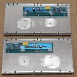
Drilled and tapped a few holes yesterday. Chassis brackets and PCBs test fitted. The back of the sink is pretty heavily grooved, so I sanded some smooth landing pads for the output transistors. Power supply will use discrete diodes bolted to the bottom plate. I'm likely to build a CLC, but not sure yet. Have to wait to have everything in hand to see how much room things will take up and decide on a layout. Front and rear panels are likely to be wooden, I have some nice pieces of figured Walnut that have been laying around waiting for a good project. I'm not sure if I'll leave the sinks in natural aluminum or give them a light coat of black paint.
Not much else to do right now but wait for Cinemag transformers to arrive and Antek transformers to be back in stock.
Not much else to do right now but wait for Cinemag transformers to arrive and Antek transformers to be back in stock.
Attachments
Last edited:
Pass DIY Addict
Joined 2000
Paid Member
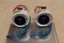
Antek goodies arrived (400VA with 18v secondaries). 300VA still not in stock and I figured the 400VA would sag less with the load, keeping the PSU closer to the recommended 22.5V or a little more.
Am I asking for trouble by aiming the center axis of the transformer directly at the Cinemag transformers? I mounted them with a brass center bolt. I was trying to preserve extra space on the chassis floor for a potential CLC by standing the transformers on edge, but I'm thinking this arrangement with the power transformers might be inviting trouble elsewhere. Any thoughts? Thanks!
Am I asking for trouble by aiming the center axis of the transformer directly at the Cinemag transformers? I mounted them with a brass center bolt. I was trying to preserve extra space on the chassis floor for a potential CLC by standing the transformers on edge, but I'm thinking this arrangement with the power transformers might be inviting trouble elsewhere. Any thoughts? Thanks!
Attachments
Last edited:
see here for inspiration, post #908
https://www.diyaudio.com/community/threads/ludef.369990/post-6997306
https://www.diyaudio.com/community/threads/ludef.369990/post-6997306
Hi Eric,
I have 2 x 400 VA Toroidy transformers mounted at the front of my case exactly in the way you're proposing to mount the transformers, and the Cinemags at the back.
Totally silent. Even on 100 dB/W speakers.
Best regards, Claas
I have 2 x 400 VA Toroidy transformers mounted at the front of my case exactly in the way you're proposing to mount the transformers, and the Cinemags at the back.
Totally silent. Even on 100 dB/W speakers.
Best regards, Claas
Pass DIY Addict
Joined 2000
Paid Member
Awesome! Thanks, guys! Glad to know I’m not inviting problems, especially because I won’t be able to tell until after all of the work is done…
- Home
- Amplifiers
- Pass Labs
- Babelfish M25, SissySIT - general building tips and tricks