Funda-Mental questions
Choky and BillWW
1. Bill, did your Aleph variant use Choky's Constant Current supply (the BC556's) or the Aleph-based one (IRF9610 based)?
2. Bill and Choky, and I suppose anyone else regarding this, because it looks pretty simple: What voltage capacitors should I use for the 220uF capacitors in the Babbelfish (C5 and C7) or in an Aleph (C9 and C10 on the Aleph 5 schematic). What sort of voltage is across them? Bill, maybe could you put a meter across them and see what it reads please?
Regards,
George.
Re: Funda-Mental questions
1. for my knowledge-Bill use J176 also for CCS
2. 35V is fine ,maybe even 25....
GeorgeBoles said:Choky and BillWW
1. Bill, did your Aleph variant use Choky's Constant Current supply (the BC556's) or the Aleph-based one (IRF9610 based)?
2. Bill and Choky, and I suppose anyone else regarding this, because it looks pretty simple: What voltage capacitors should I use for the 220uF capacitors in the Babbelfish (C5 and C7) or in an Aleph (C9 and C10 on the Aleph 5 schematic). What sort of voltage is across them? Bill, maybe could you put a meter across them and see what it reads please?
Regards,
George.
1. for my knowledge-Bill use J176 also for CCS
2. 35V is fine ,maybe even 25....
Re: Funda-Mental questions
Metering the two 220uF,
One had .7 volts, while the other was 15 or 16 volts. The schematics in the past usually have shown 50 volt, but anyways, the highest value was 16 volts.
My latest Aleph Jfet version, I have been too lazy to post on, but I am now using the irf9610 original current source that the Alephs use. I replaced the 9 volt zener with 4 3.0 volt LEDs which I adjusted to 9.0 volts.
I found the original 390 ohm resister for the current adjusted to the LTP differential sounded the best with the original Aleph value.
I did not like 392 ohms, it made things sound too bright and messed up on listening to jazz music with the snapping of someone's fingers sounding more like a drum tap.
After adjusting to 390 ohms, it sounded like a thumb and finger snapping like it should be.
Choky was correct again. Ignore my previous way of adjusting in my pdf thread from "the next pass shoot out in salt lake city."
Adjusting the 390 ohm resister modulated the differential just as well as my other attempt in my pdf, so there is no need to use my other method.
Just adjust the LED voltage to 9.0 volts with that previous 4.75 K ohm resister that was below the zener in the aleph schematics.
Also, I liked 820 ohms for the AC current gain resister in my Aleph 3 setup. It seems this sounds less dry, but more spacious below the 50 percent AC current gain.
In my aleph, I personally used 50 volt Nonpolar electrolytic caps. With 50 volt caps, in case something happens they could withstand the rail voltages plus or minus 25 volts could reach 50 volts in a worst case scenario.
I have not tried Choky's other method. I like keeping things simple in my stock Aleph setup converted to jfet.
One other thing I have learned. The j176 for a current source or the zvp3310a were fine for the stock Aleph without being biased too hard.
I ran into problems with my resister removed to the biasing of the output mosfets. Neither the zvp3310a or j176 could drive the output stage very well compared to the irf9610. I think the current source does not matter like Choky and Jh6you had previously suggested. After playing with modulating my differential LTP, it seems like the irf9610 could be left in place for your jfet conversion.
Regards, Bill 🙂
GeorgeBoles said:Choky and BillWW
1. Bill, did your Aleph variant use Choky's Constant Current supply (the BC556's) or the Aleph-based one (IRF9610 based)?
2. Bill and Choky, and I suppose anyone else regarding this, because it looks pretty simple: What voltage capacitors should I use for the 220uF capacitors in the Babbelfish (C5 and C7) or in an Aleph (C9 and C10 on the Aleph 5 schematic). What sort of voltage is across them? Bill, maybe could you put a meter across them and see what it reads please?
Regards,
George.
Metering the two 220uF,
One had .7 volts, while the other was 15 or 16 volts. The schematics in the past usually have shown 50 volt, but anyways, the highest value was 16 volts.
My latest Aleph Jfet version, I have been too lazy to post on, but I am now using the irf9610 original current source that the Alephs use. I replaced the 9 volt zener with 4 3.0 volt LEDs which I adjusted to 9.0 volts.
I found the original 390 ohm resister for the current adjusted to the LTP differential sounded the best with the original Aleph value.
I did not like 392 ohms, it made things sound too bright and messed up on listening to jazz music with the snapping of someone's fingers sounding more like a drum tap.
After adjusting to 390 ohms, it sounded like a thumb and finger snapping like it should be.
Choky was correct again. Ignore my previous way of adjusting in my pdf thread from "the next pass shoot out in salt lake city."
Adjusting the 390 ohm resister modulated the differential just as well as my other attempt in my pdf, so there is no need to use my other method.
Just adjust the LED voltage to 9.0 volts with that previous 4.75 K ohm resister that was below the zener in the aleph schematics.
Also, I liked 820 ohms for the AC current gain resister in my Aleph 3 setup. It seems this sounds less dry, but more spacious below the 50 percent AC current gain.
In my aleph, I personally used 50 volt Nonpolar electrolytic caps. With 50 volt caps, in case something happens they could withstand the rail voltages plus or minus 25 volts could reach 50 volts in a worst case scenario.
I have not tried Choky's other method. I like keeping things simple in my stock Aleph setup converted to jfet.
One other thing I have learned. The j176 for a current source or the zvp3310a were fine for the stock Aleph without being biased too hard.
I ran into problems with my resister removed to the biasing of the output mosfets. Neither the zvp3310a or j176 could drive the output stage very well compared to the irf9610. I think the current source does not matter like Choky and Jh6you had previously suggested. After playing with modulating my differential LTP, it seems like the irf9610 could be left in place for your jfet conversion.
Regards, Bill 🙂
Re: Re: Funda-Mental questions
make another pdf 😉
BillWW said:
Ignore my previous way of adjusting in my pdf thread from "the next pass shoot out in salt lake city."
Regards, Bill 🙂
make another pdf 😉
aleph 3 to jfet front end pdf
Choky, I will have to work on that maybe today and could release it on your thread or mine.
I have learned to keep it very simple now and would be a lot easier for most people to try out now.
Essentially, they would only need to change the differential with the new resister values and one 220 dc coupled cap to a film or in my case I used a vitamin Q 2.5 uF oil in paper cap for my feedback capacitor. That sounded smoother than the Mylar 2.2 uF capacitor, although the vitamin Q 300 + volt capacitor is rather large.
The orange colored film Mylar sounded the next best to my listening tests though.
I am ready to build a finished copy of my test Aleph to a nicer presentable case now.
I have kept playing with the AC current gain. My 50 percent AC current gain turned out to be 810 ohms. 820 is just slightly less than 50 percent AC gain. I have further tried 950 ohms and that has a little more detail in the highs, so maybe I will leave it adjusted there for a while.
With a lower ohm value, like 500 or 750 ohms my Aleph AC current gain seems to make the amp sound dry and not as musical with higher 820 or 950 ohm resistance for the AC current gain.
950 ohms seems to bring out the depth in recordings a little more better than the 820 ohms. I will need to check the square wave with my brother's 400Mhz scope. The cheaper 60Mhz scope needed a new probe and could not reliably check my amp. The good thing with his nicer scope, my signal generator tested fine out to 210Khz on the square wave form. His prope on the 400Mhz scope is much better than his older 60Mhz setup.
Have fun, playing with jfets. I really like the higher input impedance, for multiamping and how easy they are to drive by a preamp.
Over the year of playing with various fets, I find adjustments make a much greater difference than just using any of the previous zvp3310a or j176 or irf9610 in direct comparisons. Even with the nicer jfet, I found the amp could sound awful even compared to the original irf9610. Adjustments of the 390 ohm resister to the LTP is very useful. Also mandatory is the 221 ohm resister above the current source for adjusting the dc offset. Also the 750 ohm resister in the Aleph 3 for AC current gain needs a pot too for adjusting the AC gain.
You just have to find the right resistance for each device and tweak them in their working range and then adjust them to your own ears delight and then check with equipment on how well the square wave is along with ringing and oscillations etc...
Bill
Re: aleph 3 to jfet front end pdf
what else to say...........hehe except-never ending fun! 😉
 I use 0,5Uf VitQ on my compression drivers in this very moment
BillWW said:...........Choky, I will have to work on that maybe today and could release it on your thread or mine...........
Bill
what else to say...........hehe except-never ending fun! 😉
I used a vitamin Q 2.5 uF oil in paper cap for my feedback capacitor
I use 0,5Uf VitQ on my compression drivers in this very momentYou got that right, Choky🙂 By some kind of weird luck!!, (or something!) I actually happen to have a pair of originally made Babbelfish pcb's😀 Awesome😉 When the summer has passed on and soldering is tolerable again, I will put it together🙂hehe except-never ending fun!
Steen😎
steenoe said:You got that right, Choky🙂 By some kind of weird luck!!, (or something!) I actually happen to have a pair of originally made Babbelfish pcb's😀 Awesome😉 When the summer has passed on and soldering is tolerable again, I will put it together🙂
Steen😎
ya back?
nice to read you again 😉
it's even nicer to read that you'll spend time more on listening,than super fast building
btw-where you scavenge original Babelfish J pcbs?
directly from NP lab?
they certainly cost you muuuuuuuuuucho
hehe,in any case- less than KK's

Aleph 3 to jfet conversion
Okay, I worked on this article with drawing for a couple of hours. Hope those who want to try a jfet front end, will try this one, since it is the easist version yet to try out.
You could leave the original zener reference in place too, if you do not want to mess with lower noise LEDs too initially until your satisfied with your circuit running etc.
You could use the 2sj109 or j176 for the differential. I believe a perf board could hold the 2sj109 and then wire the Leads up to your circuit board via wires, would work, or just buy a 100 j176 and match them to 12.75 mA of current and solder in place of the irf9610 differential.
Here is the pdf anyways to try, which is easier than my previous version on "the Next Pass Shoot Out in Salt Lake City" pdf jfet release.
Regards, Bill
Attachments
tnx Bill.......
hm-I'm sorta Babelfishing again...
my Babelfish J is in "almost finished " stage and will stay little longer status quo........
I just think again about Oly's mini symetric amp,and I play little with Paint proggggggie :
is it Susy or not? (preamp or amp- depending of Iq and used output mosfets)....I know that's boiled water in fact-but I'm just one,not really capable to see every thread even just on Pass subboard here...
if anybody looks at this thread anymore
I'm kinda tired,but I cannot sleep-not enough food for brain today yet....I'll go to sleep when I feel that I will loose my consciousness......hehe- now I remind my self on Gray-he ends every 3. post how he sleep too little
ps.I give 80 Euros today for 22Kg (12 identical pieces) of veeeery nice heatsinks.......I already tried them with 100W/piece dissipation....after 5 min I was capable to hold my fingers for 5 secs on them.....hot?
it's summer here......I'll repeat tomorrow same test with temp. meter.......
btw comments on price?
I'm thrilled and disgusted -nice price (I think ) but payed on Junk Yard .......damn usurers!
Attachments

I am not insisting . . . Never mind . . .
Hi, Bill,
I understand that 2.2uF is the one scaled down considering the increased sizes of 22K/220K. With 2.2uF, I am thinking that it might be a bit small as a compensating cap so that we might see a minor potential happening of oscillation. I would consider minimum 10uF . . . ?
Hi, Choky,
is it Susy or not?
I think it is Susy. Nevertheless, I also think that there might be a better Susy when the 1K2/22 and 22K/2K2 are well proportioned each other . . . ?
Sure, Nelson has answers which will intentionally not be released . . . bad . . .
All, Regards
JH
jh6you said:I am not insisting . . . Never mind . . .
Hi, Bill,
I understand that 2.2uF is the one scaled down considering the increased sizes of 22K/220K. With 2.2uF, I am thinking that it might be a bit small as a compensating cap so that we might see a minor potential happening of oscillation. I would consider minimum 10uF . . . ?
Hi, Choky,
is it Susy or not?
I think it is Susy. Nevertheless, I also think that there might be a better Susy when the 1K2/22 and 22K/2K2 are well proportioned each other . . . ?
Sure, Nelson has answers which will intentionally not be released . . . bad . . .
All, Regards
JH
regarding 2U2....I think that this cap can't be cause of possible oscillations....
regarding 1k2/22 and 22k/2k2.....that values are just replicated from Oly's schmtc of his simple simetric amp; I know that some values must be changed,but in this moment I'm more interested in topology,not optimized values
regarding Master's answers- where is fun if he tell us everything about everything (and even Master can't know everything
)
choky said:
I think that this cap can't be cause of possible oscillations....
It can't be a cause . . .
It can be too small to compensate the phase shift (if any) . . .
choky said:
(and even Master can't know everything
It is too gentle to bait Master into Texas . . .
choky said:is it better now?
Wow . . . is it additional current feedback . . . ?
Regards
Aleph oscillations
jh6you and choky,
I found there were a couple of problems with my chassis. There were ground loops being formed from how the heat sinks had two mounting points forming a loop it seemed. As I isolated how they were mounted that problem went away. Using my brother's 400Mhz oscilloscope, I solved most of the problems I was having.
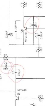
I am still playing around with compensation caps, but so far have found 1pF across the 220k feedback resister reduced my ringing, although I am going to still try checking out some other compensaton values to try.
So far, I have tried .001 uF and 680 pF across the mpsa18 fet. Either value stops my amp from oscillating, but they do affect how my square wave looks.
I would like to try the .001 uF in another position like in the original Aleph 3 schematic and see what that will do. Maybe, I can get rid of the 1 pF.
So far, the slight ringing was very minimal without the 1 pF.
I further found adjusting the 390 ohm resister below the LTP also affected that ringing peak. I was able to reduce the peak by adjusting that 390 ohm resister's position value.
I think the unstable dc offset is due to how well I matched the differential LTP pair. I am not using and resisters to assist with the jfets. Do you think that could be why they seem to drift quite a bit? No resisters for load sharing?
It seems like the irf9610 as a current source warms up much slower than the smaller To-92 fets and that causes the slower dc offset problems. The zvp3310a and j176 as currents sources were much faster on settling the dc offset compared to this irf9610 mosfet.
Bill
jh6you and choky,
I found there were a couple of problems with my chassis. There were ground loops being formed from how the heat sinks had two mounting points forming a loop it seemed. As I isolated how they were mounted that problem went away. Using my brother's 400Mhz oscilloscope, I solved most of the problems I was having.
I am still playing around with compensation caps, but so far have found 1pF across the 220k feedback resister reduced my ringing, although I am going to still try checking out some other compensaton values to try.
So far, I have tried .001 uF and 680 pF across the mpsa18 fet. Either value stops my amp from oscillating, but they do affect how my square wave looks.
I would like to try the .001 uF in another position like in the original Aleph 3 schematic and see what that will do. Maybe, I can get rid of the 1 pF.
So far, the slight ringing was very minimal without the 1 pF.
I further found adjusting the 390 ohm resister below the LTP also affected that ringing peak. I was able to reduce the peak by adjusting that 390 ohm resister's position value.
I think the unstable dc offset is due to how well I matched the differential LTP pair. I am not using and resisters to assist with the jfets. Do you think that could be why they seem to drift quite a bit? No resisters for load sharing?
It seems like the irf9610 as a current source warms up much slower than the smaller To-92 fets and that causes the slower dc offset problems. The zvp3310a and j176 as currents sources were much faster on settling the dc offset compared to this irf9610 mosfet.
Bill
Bill
As far as I remember (Papa once said), the set of (pF-value//220K) is forming a major pole (a critical frequency point), which mostly affects the stability of the amp. I would recommend to increase your 1pF to the value until you can no more see the oscillation. Even if the value goes up somewhat, the critical frequency still stays far above from the listenable top frequency.
Hope this info will be of help.
I very much appreciate your exploration . . . 🙂
Regards
JH
billww:
in what amount they affect squares?
is it audible that square waves spoiling?
you try that certainly,but for what reason you need to get rid of 1pF ?
if that cap make useful things,there is no evil in keeping it in circ
how many fets you have in output ?
that 390 ohm value is in direct connection with input capacitances of output fets ...you can also try to decrease gate resistors of output mosfets to ,say,270 ohms and see and hear what's will happen.
one of the reasons why I tried my Babelfish with just one pair of IRF150N is -in this way-tiny 2SJ109 must push and pull just one gate,no more ; Papa use 2 pairs,if memory serves me well, but Papa is Papa,and I'm just cheapskate
it's better to use them (22 to 47 ohms) resistors....sorta of local degeneration,in this case they can be helpful ; you mounted those tiny jfets back to back ,with some thermal goo between? you certainly sayed that to me already,but I can't remember....
if IRF9610 can withstand ( and it can 😉 ) without any heatsink,use it without heatsink-that will speed up thermal equilibrium;
maybe is also worthwhile to move lower leg of current adj resistor for your led string (resistor connected in series with led string) to minus supply (from gnd,as is connected now) ;that will improve CMRR and whatever -all that short acronym thingies....
few things more:
Papa sez that 500mV of DC offset on cold is normal thing for Alephs;
what I know from xperience with Babel and Oly's mini is that final adjustings are slow; steady temperature conditions (IN CASE ,or BOX -if you prefer) are preferable ,just because every temp drift of diff pair will result in DC offset drift.....
funny-let amp cook for a while,open the case,tweak it little,close the case....wait ....measure...open the case,tweak,close the case.....wait,measure......and again......
when I tested my Babbbbb...it was 3D on so-so heatsink,helped with one lazy Papst.....after some time I spotted that DC offset wanders all the time,accordingly to moving my hands with probes around 3D mess.....with hands I change direction of little breeze on top of heatsink.....after I realized that ,I leave just DC offset DMM connected with clips and take one "Drina without filter" brake,just looking on DMM.....offset was pretty steady,changing value up or down only when I increase or decrease speed of fan....
conclusion-input stage (pcb) must be in relatively closed box...
btw-offset is usually overrated thing....everything from +150mV to -150mV is pretty normal....without DC servo ,with furnace -like amp,nobody can't do better.....
remember Papa's engineering rule- "good enough is enough"
(even if I didn't see that Papa wrote that sentence, I think that is just in his wakoo style )
So far, I have tried .001 uF and 680 pF across the mpsa18 fet. Either value stops my amp from oscillating, but they do affect how my square wave looks.
in what amount they affect squares?
is it audible that square waves spoiling?
I would like to try the .001 uF in another position like in the original Aleph 3 schematic and see what that will do. Maybe, I can get rid of the 1 pF.
you try that certainly,but for what reason you need to get rid of 1pF ?
if that cap make useful things,there is no evil in keeping it in circ
I further found adjusting the 390 ohm resister below the LTP also affected that ringing peak. I was able to reduce the peak by adjusting that 390 ohm resister's position value.
how many fets you have in output ?
that 390 ohm value is in direct connection with input capacitances of output fets ...you can also try to decrease gate resistors of output mosfets to ,say,270 ohms and see and hear what's will happen.
one of the reasons why I tried my Babelfish with just one pair of IRF150N is -in this way-tiny 2SJ109 must push and pull just one gate,no more ; Papa use 2 pairs,if memory serves me well, but Papa is Papa,and I'm just cheapskate
I think the unstable dc offset is due to how well I matched the differential LTP pair. I am not using and resisters to assist with the jfets. Do you think that could be why they seem to drift quite a bit? No resisters for load sharing?
it's better to use them (22 to 47 ohms) resistors....sorta of local degeneration,in this case they can be helpful ; you mounted those tiny jfets back to back ,with some thermal goo between? you certainly sayed that to me already,but I can't remember....
It seems like the irf9610 as a current source warms up much slower than the smaller To-92 fets and that causes the slower dc offset problems. The zvp3310a and j176 as currents sources were much faster on settling the dc offset compared to this irf9610 mosfet.
if IRF9610 can withstand ( and it can 😉 ) without any heatsink,use it without heatsink-that will speed up thermal equilibrium;
maybe is also worthwhile to move lower leg of current adj resistor for your led string (resistor connected in series with led string) to minus supply (from gnd,as is connected now) ;that will improve CMRR and whatever -all that short acronym thingies....
few things more:
Papa sez that 500mV of DC offset on cold is normal thing for Alephs;
what I know from xperience with Babel and Oly's mini is that final adjustings are slow; steady temperature conditions (IN CASE ,or BOX -if you prefer) are preferable ,just because every temp drift of diff pair will result in DC offset drift.....
funny-let amp cook for a while,open the case,tweak it little,close the case....wait ....measure...open the case,tweak,close the case.....wait,measure......and again......
when I tested my Babbbbb...it was 3D on so-so heatsink,helped with one lazy Papst.....after some time I spotted that DC offset wanders all the time,accordingly to moving my hands with probes around 3D mess.....with hands I change direction of little breeze on top of heatsink.....after I realized that ,I leave just DC offset DMM connected with clips and take one "Drina without filter" brake,just looking on DMM.....offset was pretty steady,changing value up or down only when I increase or decrease speed of fan....
conclusion-input stage (pcb) must be in relatively closed box...
btw-offset is usually overrated thing....everything from +150mV to -150mV is pretty normal....without DC servo ,with furnace -like amp,nobody can't do better.....
remember Papa's engineering rule- "good enough is enough"
(even if I didn't see that Papa wrote that sentence, I think that is just in his wakoo style
)Attachments
jh6you said:
Wow . . . is it additional current feedback . . . ?
Regards
ya mean on McM resistors?
hehe nothing else than McMillan (memory?!@#$) resistors to help DC offset
It is too gentle to bait Master into Texas . . .
why not?
he completely spoiled too much kids already


square wave photos
I will try and get some photos of how my square wave looks at 1K and 10K and 100K later tonight.
I should clarify to Choky, I placed the 680 pF over the base and collector of the mpsa18. I also tried .001 uF in this same place to see how the square wave would looked.
The 1 pF was placed over the 220K feedback resister to reduce a slight sharp peak or ringing on the square wave. I noticed it rounded the edge of the square wave more though, so I hope to get rid of this peak on the square wave and less rounding of the square wave.
Now that I have a quality scope, I am actually enjoying working on this amp and seeing how it is behaving.
As long as my heatsinks are hot I am happy. I seen my amp in much worse shape not working. 😱
I am just fine tuning things now. The amp is very predicitable at this time and there really are not surprises any longer.
Bill
- Status
- Not open for further replies.
- Home
- Amplifiers
- Pass Labs
- Babbelfish J PCBs