Zen Mod said:
why don't you visit them,to be sure that you get what you need?
I don't want this to sound wrong, but my time is more valuable to me than the money I just spent on a few transistors, especially when you add in the gas money to go down there.
I am assumming they only have one grade of 109 there, now that you mention it

I guess I will see what I get.
Randy
Re: Layout for slightly modified babbelfish
OK-just one note :
compare current and other data netween IRFP150 and 240 (you choose to use) . I have also this decision to make,and I choose just one gate to be driven.
looking at current and dissipation,seems that 150 is good as two 240s, under condition that you cool them correctly.
I dunno what trick Papa have in his sleeve, or in which way exactly he choose to drive two gates (maybe I'm .....or-I was.....overreacting,but that was my decision- or compromise ,if you wish).
I didn't try to drive two output gates with sisy 5mA.
and I'll not
anyway-I don't need even this 30W from Babelfish.........5 maybe
is there any way to put just half of output mosfet on output.....literally ?

cviller said:
Great document.
😀
I have made a layout for the fish with two pairs. This will be my first power amp, so I would really appreciate, if some of the more experienced amp builders would spend a few minutes on my layout and offer their comments.
The board is single sided and designed for 40cm heatsinks. Dark blue traces are + AND - rails. Light blue is ground and red is everything else. The brown is just a jumper.
Layout:
http://viller.org/audio/2007jan_jfish/jfish_c.pdf
Schematics:
http://viller.org/audio/2007jan_jfish/alephjfish_r.sch
http://viller.org/audio/2007jan_jfish/alephjfish_l.sch
BTW: Please don't waste your time trying to make this into a B/W version - just mail me and I'll send it to you. 😉
OK-just one note :
compare current and other data netween IRFP150 and 240 (you choose to use) . I have also this decision to make,and I choose just one gate to be driven.
looking at current and dissipation,seems that 150 is good as two 240s, under condition that you cool them correctly.
I dunno what trick Papa have in his sleeve, or in which way exactly he choose to drive two gates (maybe I'm .....or-I was.....overreacting,but that was my decision- or compromise ,if you wish).
I didn't try to drive two output gates with sisy 5mA.
and I'll not
anyway-I don't need even this 30W from Babelfish.........5 maybe
is there any way to put just half of output mosfet on output.....literally ?
just to add:
mebbe one day I'll spend some time in establishing exact symmetry in input impedances etc ,in case of using bal input .
in a meantime -it's good enough in this way
add. No.2
if you use just two mosfets in output ,you don't need to match them.......perfect for lazy bstrd like me
mebbe one day I'll spend some time in establishing exact symmetry in input impedances etc ,in case of using bal input .
in a meantime -it's good enough in this way
add. No.2
if you use just two mosfets in output ,you don't need to match them.......perfect for lazy bstrd like me
randytsuch said:
I don't want this to sound wrong, but my time is more valuable to me than the money I just spent on a few transistors, especially when you add in the gas money to go down there.
I am assumming they only have one grade of 109 there, now that you mention it
I guess I will see what I get.
Randy
your choice ;
you must also count on time spent on amp making ;
good preparation is also part of that process (look at my case-I prepare mine so thoroughly that I didn't even make it ,yet
)you can use BL or V iterations ; GR certainly not
in case that you receive wrong type , you'll probably spend more time later,than money.
at least-give them a call
Zen Mod said:
your choice ;
you must also count on time spent on amp making ;
good preparation is also part of that process (look at my case-I prepare mine so thoroughly that I didn't even make it ,yet
you can use BL or V iterations ; GR certainly not
in case that you receive wrong type , you'll probably spend more time later,than money.
at least-give them a call
Hi
I emailed them, their warehouse is closed for the day, they will let me know what the type is tomorrow.
And the bad news. They only have a few left in stock, enough for my order. But, they may be able to get more, he asked if I wanted more, but I declined.
Randy
Re: Re: Layout for slightly modified babbelfish
Thanks for your comments. I think the Ciss of two 240 should be ok - the combination only adds 50% capacitance compared to one 150. The transconductance seems to be in the same range, although I think my simulations tries to tell me that I should lower the gain somehow.
And what about papas remark:
http://www.diyaudio.com/forums/showthread.php?postid=1111790#post1111790
Is he pointing us to something along the lines of attached schem?
It seems to flatten the frequency response slightly and make transitions on square signals faster.
I have added R33, R34 and C13. The capacitor takes limits the ringing on the edges of square signals. The values I have put in a are not calculated and I wouldn't consider them optimal, but you might get the idea.
Zen Mod said:
OK-just one note :
compare current and other data netween IRFP150 and 240 (you choose to use) . I have also this decision to make,and I choose just one gate to be driven.
looking at current and dissipation,seems that 150 is good as two 240s, under condition that you cool them correctly.
I dunno what trick Papa have in his sleeve, or in which way exactly he choose to drive two gates (maybe I'm .....or-I was.....overreacting,but that was my decision- or compromise ,if you wish).
I didn't try to drive two output gates with sisy 5mA.
and I'll not
anyway-I don't need even this 30W from Babelfish.........5 maybe
is there any way to put just half of output mosfet on output.....literally ?
Thanks for your comments. I think the Ciss of two 240 should be ok - the combination only adds 50% capacitance compared to one 150. The transconductance seems to be in the same range, although I think my simulations tries to tell me that I should lower the gain somehow.
And what about papas remark:
http://www.diyaudio.com/forums/showthread.php?postid=1111790#post1111790
Is he pointing us to something along the lines of attached schem?
It seems to flatten the frequency response slightly and make transitions on square signals faster.
I have added R33, R34 and C13. The capacitor takes limits the ringing on the edges of square signals. The values I have put in a are not calculated and I wouldn't consider them optimal, but you might get the idea.
Attachments
Hi guys
The vendor just sent me a picture of the part, it is the 2SJ109 in the BL grade 🙂
Sorry they don't have more, I would not have posted the link if I had known they only had a few left.
They did think there are more out there, but from this thread I know that may not mean anything.
If enough people ask this place for the part, they may try to buy some more.
Randy
Hey folks, I think I'll give this fish a fry. I just ordered some 2SJ109BL's
from B & D Enterprises in Russel P.A. They have 12 left... http://www.bdent.com/search/part.jsp?partnum=2SJ109
-Mal
p.s. I hope my casework will be atleast half as "UGLY" as Steen's A-X's
from B & D Enterprises in Russel P.A. They have 12 left...
http://www.bdent.com/search/part.jsp?partnum=2SJ109-Mal
p.s. I hope my casework will be atleast half as "UGLY" as Steen's A-X's
Malotron said:They have 12 left
Yikes, at those prices i'll enjoy watching my popcorn later this evening.
Left Click my red nose:
jacco vermeulen said:
Yikes, at those prices i'll enjoy watching my popcorn later this evening.
........................
give us a pic of that gold mine 😉
btw-are spks left and right in your tool room Dynaudios?
Good and bad news
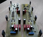
I built my version of this fishing project this weekend, but the results are mixed. The sound is incredible - the first channel I tested had some dc on the output 80mV, but I tried it with my speakers anyways. I was astonished the clean sound and all the details!
Now the problem is the ripple on my supply and output. I only have one psu for both channels. The crc for each rail looks like this:
2x15mF -> 5x 1R -> 4x15mF
The ripple with both channels running is just below 100mV on each rail (measured with my scope).
The ripple with only one channel running seems to be approx 80% of one rail ripple. I have looked around with a probe and the only place that seems to be without ripple is the grounded input and source on jfets.
Any suggestions to what I should look for? Shouldn't it be possible to reject 100mV ripple?
I have attached a picture of my boards so Choky can give his usual comment. And I will post my schematics in few minutes.
Attachments

first thing first: ugly!
second - where are heatsinks?
third- on first sight,schm looks good ; for later-try to vary 22 ohms source degeneration resistors, down and up,just to see (hear) can you spot any difference
next- you have hum now even with one channel only,and you have nada hum in first test?
if yes- you definitely have gnd loop somewhere ;
tell me - xformer,graetz,caps,res,caps ........?
have you some sisy xformer here
play little with PSUd if you have time
and-try with 3x15mF-0R2-3x15mF
and-what's Iq?
I have uploaded a few pics here:
http://viller.org/audio/2007jan_jfish/hum/
Yes, there was no hum before, but I used a water boiler in series with mains so it might have done some strange tricks.
I have used zalman grease and mica. The transformers are two of the 10x17V 1.5A I have been talking about a few times. They don't make any bad noises and doesn't get hot at all.
http://viller.org/audio/2007jan_jfish/hum/
next- you have hum now even with one channel only,and you have nada hum in first test?
if yes- you definitely have gnd loop somewhere ;
Yes, there was no hum before, but I used a water boiler in series with mains so it might have done some strange tricks.
tell me - xformer,graetz,caps,res,caps ........?
I have used zalman grease and mica. The transformers are two of the 10x17V 1.5A I have been talking about a few times. They don't make any bad noises and doesn't get hot at all.
star ground-make it fat and precise
everything goes to star ground ,separately :
spk minus wire
pcb ground
input connector ground (not connected on pcb,just on connector side!)
and-that's probably "everything" ; 3 ground wires for each channel
if you make like this,you probably will not have any gnd loop
clear or you need sketch?
if you already know this,hehe- I hope that some noob will read this somewhere in time....
you didn't answer - what's Iq?
EDIT:
now,looking at first picture,I can see that you have 3 gnd connections to each pcb............power ground wire (from PS),speaker ground wire (from pcb to spk (scope probe gnd connected to it) ) and shielded and input cable..
as I say (often to my self 😉 ) ......no-no...........ya really need just one gnd wire to pcb.......(from PS central gnd point to pcb)
try it
star ground-make it fat and precise
everything goes to star ground ,separately :
spk minus wire
pcb ground
input connector ground (not connected on pcb,just on connector side!)
and-that's probably "everything" ; 3 ground wires for each channel
if you make like this,you probably will not have any gnd loop
clear or you need sketch?
What about rectifier bridge? Can I make the psu pcb starground?
I don't really like the idea of ditching the shield on input connectors, but I guess I might have to.... 🙁
you didn't answer - what's Iq?
Sorry about that. I didn't answer cos I was not sure if you just meant the current through my transistors or something else. I have close to 1A through each transistor.
try it
I will. 😉
Thanks for your suggestions!
cviller said:
What about rectifier bridge? Can I make the psu pcb starground?
I don't really like the idea of ditching the shield on input connectors, but I guess I might have to.... 🙁
Sorry about that. I didn't answer cos I was not sure if you just meant the current through my transistors or something else. I have close to 1A through each transistor.
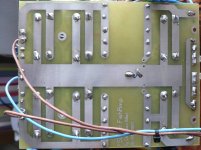
gimme pic of copper side of PSU pcb and I'll point you to adequate point .............center between cap's grounds...
ditching the shield.........think and re-think........do you really need g-loop?
grounding shield just at connector side is 100% effective...........shield is still shield and not conductor for g-loop 😉
got it,regarding Iq
Zen Mod said:
gimme pic of copper side of PSU pcb and I'll point you to adequate point .............center between cap's grounds...
ditching the shield.........think and re-think........do you really need g-loop?
grounding shield just at connector side is 100% effective...........shield is still shield and not conductor for g-loop 😉
I think shield only works effectively if it is return-path for signal...

I have attached the underside of my psu. The left side is output and right side is input. The two grounded leads just to the right of the middle are from the rectifier bridges. Should I place starground in the middle to the left?
I have tried to measure hum on ground nodes, but haven't found anything. I will however still try the starground, although I think the root cause is somewhere else.
Attachments
cviller said:
I think shield only works effectively if it is return-path for signal...
yes-if input connector is isolated from case and not grounded to star ground
...... The two grounded leads just to the right of the middle are from the rectifier bridges. ......
place good enough for all ground wires
Thanks Choky for helping me with this!
I tried to move all ground wires to gnd terminal on my psu board and only running one channel but I didn't see any noticeable improvements, but I discovered something else. There is a very large difference in my CCS transistors source resistor voltages. One reads 450mV whilst the other is 200mV (across a 0.47 resistor).
I did match all my transistors to within 0.01V at 1A and 20sek. Could it be my resistors or should I try with some different transistors? The gate voltages were the same in reference to ground.
- Status
- Not open for further replies.
- Home
- Amplifiers
- Pass Labs
- Babbelfish J PCBs