This probably isn't directly relevant but here's an example. I have a passive preamp that is nothing more than a pair of 1:8 turns ratio transformers with a 10k pot on the secondary. With a 10k Zin amp, the impedance reflected to the primary can be quite low- 78 ohms by one calculation. A few of my sources can handle this, but one, a cheapo Logitech bluetooth adapter, cannot. The sound is fuzzy and tremendously distorted. So in your case, if the Zin of your WLS is somehow 'wrong' like maybe a mistaken input resistance value somewhere, it could cause loading problems with some sources but not others.I know the reason is me, my misunderstanding but I cannot figure it out: why the Pass pre I built with the Burning Amp board works and works well no matter in which system I put it but my build of Waynes Line Stage makes a hidious noise in one system and is fine when used with a Pass (F6) amp and ordinary CD player.
I would think that it would be all or nothing, I made a mistake somewhere but that WLS is a gem in one systen and Seriously non-funtional in the other. While the BA pre is unflappable. Oh, to be fair the WLS uses output caps just like the BA... the DC offset was not tamable with just the pots so that difference is not a difference. I don't understand, what makes a preamp just a hidious noise maker only in some situations? Please, Help me understand!
OK
thing I can't remember, without looking at schm, is what WLS gain is set to
it is (more or less, more in this case, I can err just for 1 ) set with ratio of R16/R17
now, you can change R16 to 10K and I believe it is already done without sonsequences
change R18 to 330K - 470K and increase Vol Pot value to 100K ........ or continue to use 60K as you already have it ...... it must be highest possible thinking of CAL mediocre Rout of 2K
test entire setup ( WLS + Amp) with any other source, then with CAL
if you still have problems using CAL, Dumpster time .....
edit: as ranshdow typed in meantime, check all components on WLS, resistors in first place
thing I can't remember, without looking at schm, is what WLS gain is set to
it is (more or less, more in this case, I can err just for 1
) set with ratio of R16/R17now, you can change R16 to 10K and I believe it is already done without sonsequences
change R18 to 330K - 470K and increase Vol Pot value to 100K ........ or continue to use 60K as you already have it ...... it must be highest possible thinking of CAL mediocre Rout of 2K
test entire setup ( WLS + Amp) with any other source, then with CAL
if you still have problems using CAL, Dumpster time .....
edit: as ranshdow typed in meantime, check all components on WLS, resistors in first place
I will check my resistor values, mistakes can be made anytime I know. Along those lines... I am really wondering why running a variable resistor/pot in parallel with R18 (100k) is a good way to adjust volume. I am a noob, so forgive me here but... if you put a pot in parallel with a 100K resistor and turn the pot to minimum, say 1 Ohm then the incoming signal sees only (about) that 1 Ohm. Isn't that the way resistors in parallel work?
nope
find any schematic with vol pot shown and see where input signal is connected
Rin of line stage itself is playin' somewhat with Vol Pot action, but 100K of WLS Rin is proper for Vol pots up to 25K, anything above that calls for increasing 100K resistor I already mentioned
find any schematic with vol pot shown and see where input signal is connected
Rin of line stage itself is playin' somewhat with Vol Pot action, but 100K of WLS Rin is proper for Vol pots up to 25K, anything above that calls for increasing 100K resistor I already mentioned
Zen, my friend, I have searched a LONG time for such a schematic... no can find. It is Super frustrating.
In almost every schematic for tube amps they just put in a variable resistor (pot) on the plus signal to ground and vary the input impedance that way.
In almost every schematic for tube amps they just put in a variable resistor (pot) on the plus signal to ground and vary the input impedance that way.
He said he added caps I think. My first one was like that, solder touch up and deep cleaning around the tiny bit helped a lot. Those tiny critters seem very affected by left goo and solder residue. If it still feels sticky, you are not done.If the DC offset was not tamable with just the pots, what did you do to tame it?
Russellc
Gain approx 3,7x if I remember correctly.OK
thing I can't remember, without looking at schm, is what WLS gain is set to
it is (more or less, more in this case, I can err just for 1
now, you can change R16 to 10K and I believe it is already done without sonsequences
change R18 to 330K - 470K and increase Vol Pot value to 100K ........ or continue to use 60K as you already have it ...... it must be highest possible thinking of CAL mediocre Rout of 2K
test entire setup ( WLS + Amp) with any other source, then with CAL
if you still have problems using CAL, Dumpster time .....
edit: as ranshdow typed in meantime, check all components on WLS, resistors in first place
27k/10k+1 =3,7
What is DAC source? Can you change the volume there or on the DAC itself? That will do the same as volume pot (at least for testing purposes, ignoring SNR). All you need is -5dB to match nominal output between 3.5 and 2V
Thank you everyone!
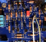
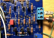
The DAC is NOT adjustable :-(. I did use output caps seen in picture below. I do not see or feel any "goo" on my tiny JDET soldering (see Pics).
Best of all is the formula I need to determine gain! Who Hoo! Now what I seem to need is a clear indication of how to attach a pot for volume control. I am thinking I have done something seriously noob!
Attachments
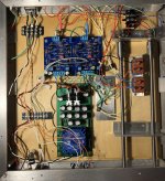
I don’t think I would extend the bias led to the front panel. Just add another one off the power supply. The one you extended is in the audio path.
andynor... you are suggesting that I add resistance with a pot BEFORE the circuit... would using a pot/variable resistor in place of R20 fulfill that requirement?
Zen, my friend, I have searched a LONG time for such a schematic... no can find. It is Super frustrating.
In almost every schematic for tube amps they just put in a variable resistor (pot) on the plus signal to ground and vary the input impedance that way.
read this, at least page or two:
The Poor Serbian Man's Optical Attenuator
Oh Zen, you have sent a college level course to a high school freshman. All I want is a WLS schematic like the one I posted except that it marks the attachment points for a POT to control volume. I get that your calculations say 25k pot for R18 at 100k. That's cool. I can change R18 to 330K and use a 100K pot, that's cool too. I just don't know where to connect wires dude, it's got to be made really simple ;-)
No, I just missed the whole pic and misunderstood your wiring completely. Please disregard, I tried to delete but too late.andynor... you are suggesting that I add resistance with a pot BEFORE the circuit... would using a pot/variable resistor in place of R20 fulfill that requirement?
you are getting good help, but two observations:
1: the boards LED’s are extended quite long. These are a part of the boards biasing circuit. I am not sure mounting them off board is wise, as DCR will increase as well as inductance maybe being added. Also: sure you have the correct Lite-On LED’s? Guessing you do.
2: Is the DC offset unstable? Is the offset affected when you turn the volume pot? If so: I recommend checking all JFETs are working as they should. Checking resistance between the JFET legs and the next point on the PCB/next resistor leg etc, will tell a great deal about whether the seemingly good solder job works as good as it looks 🙂
Oh Zen, you have sent a college level course to a high school freshman. All I want is a WLS schematic like the one I posted except that it marks the attachment points for a POT to control volume. I get that your calculations say 25k pot for R18 at 100k. That's cool. I can change R18 to 330K and use a 100K pot, that's cool too. I just don't know where to connect wires dude, it's got to be made really simple ;-)
well, I said - read basics
basics seem to indicate that RCA plus encounters POT. at one end, (other end free) and wiper connected to + terminal of board. 'Forms a voltage divider, yes?
yup
top of the pot -signal input
bottom of the pot - GND
wiper - signal output
now, regarding Rout of pot itself, worst case is when wiper is exactly on mid position
in that case Rout is (Rpot/2) // (Rpot/2)
you said - 60K
so, Rout of your pot is in worst 15K ....... in my book it calls at least for 750K of input impedance of next stage ....... which is not practical
OK, I got one thing right, yea! Now, question is about R18. IS that part of the formula? because if R18 remains soldered the stuff gets more complex as the bottom half of the pot is in parallel with R18 while the top forms an assistant resistance to R20.
I'm sure of the part number on my pots but they do max at 58k... though half of the rotation splits into 3k and 55k. I CAN figure out which end is which so do I want the first half of the rotation to be the 3k (slow) end.?
I'm sure of the part number on my pots but they do max at 58k... though half of the rotation splits into 3k and 55k. I CAN figure out which end is which so do I want the first half of the rotation to be the 3k (slow) end.?
- Home
- Amplifiers
- Pass Labs
- BA pre good... WLS2018, not so good