Hi,
another question...
Is it possible to create distant bias/offset test point without creating troubles like hum, noise or oscilliation?
Damien
another question...
Is it possible to create distant bias/offset test point without creating troubles like hum, noise or oscilliation?
Damien
What voltage swing is the BAF 3 capable of as a pre amp.
I have built the DIYAUDIO board...used DIYAUDIO matched lsj74 and lsk 170 grade c jfets.
the rails as measured by my voltmeter are 20 volt rails. putting in a 1 volt signal(measured by my voltmeter) gets a 9 volt output.
I have adjusted p1 and p2 using the prescribed method, as well as looking at the waveform on an oscilliscope. I can't get much past 9 volts when clipping starts.
I would have thought that I would get more voltage swing. Should I be able to swing voltage closer to the rails??
to audionut #182
I think you use BA-3 as a input stage for a BA-3 poweramp or
BA-3 inputstage as preamp?
PSU should have symmetrical voltage: +/- 20 V?
And I think voltage swing should be higher? You don't get up to max rail voltage
(positive or negative) but close.
Only some thoughts.
Greets
Dirk
I think you use BA-3 as a input stage for a BA-3 poweramp or
BA-3 inputstage as preamp?
PSU should have symmetrical voltage: +/- 20 V?
And I think voltage swing should be higher? You don't get up to max rail voltage
(positive or negative) but close.
Only some thoughts.
Greets
Dirk
Has to be BA-3 inputstage - you are using complementary JFets.
So, you will need symmetrical voltages: + 20 V and - 20 V and ground.
Greets
Dirk
So, you will need symmetrical voltages: + 20 V and - 20 V and ground.
Greets
Dirk
Thanks for your reply...it is the BA-3 gain stage that I want to use as a pre-amp for a MO FO amp
the rails are +20 volts and -20 volts to the gain stage. I can't seem get much more than a 9 volt swing before clipping...shouldn't I be able to get say a 35 volt swing??
I see that I probably have this question in the wrong thread
the rails are +20 volts and -20 volts to the gain stage. I can't seem get much more than a 9 volt swing before clipping...shouldn't I be able to get say a 35 volt swing??
I see that I probably have this question in the wrong thread
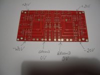
Yes...that is the board....
So I am wondering, with properly made boards, how close to the rails should I be able to drive the output...
So I am wondering, with properly made boards, how close to the rails should I be able to drive the output...
The BA-3 as a preamp has plenty of gain, it will easily overdrive an F5 with a CD player input.
So...I have the BA-3 board built and running on plus and minus 30v rails...
Using DIY Audio matched JFETs as prescribed by the DIY Audio store.
Using the FQP 3P20 FQP 3N30 MOsfets With 1000 ohm p1 and p2
Bias through the MOSFETs perfectly balanced.
1000hz sign wave going the pre amp through looks very pretty on the scope.
But here is my problem, or maybe not a problem...
1volt in equals 9.3 volts out. I would have thought 1 volt in would equal 30 volts out if the gain in the pre amp is 30.
Is my thinking wrong, or am I not getting enough gain out of the pre amp?
Thanks
you can write again and again and again
without replying on basic questions about your build , its hard that you'll get any useful answer
without replying on basic questions about your build , its hard that you'll get any useful answer
Thanks for your response Zen Mod...
You had asked earlier "exact schematic, which one?"
The schematic is the one that comes up in the DIYAUDIO store in the boards section, titled "Burning Amplifier Gain Stage for BA-3. The Schematic page is titled BA-3. The accompanying BOM is titled P-BAGSN-1V20.
I will attach the schematic in a little while...
Here is the link to the schematic
https://cdn.shopify.com/s/files/1/1006/5046/files/P-BAGSN-1V20-schematic.pdf
https://cdn.shopify.com/s/files/1/1006/5046/files/P-BAGSN-1V20-schematic.pdf
ok
here it is , attached (linked form 6L6's first post of this very thread)
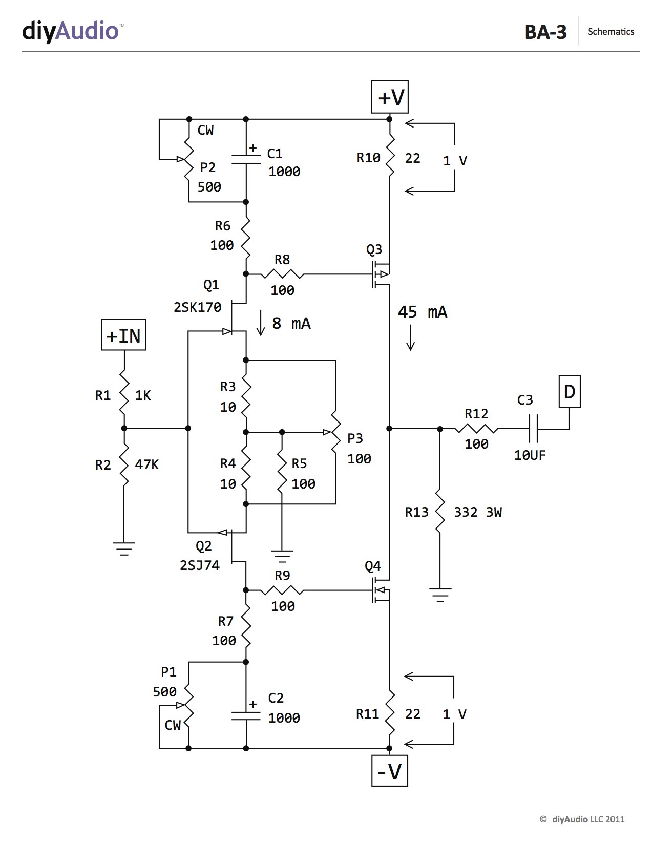
now , what's voltage across R6 and R7 ?
do you have 1V across R10 and R11 ?
for full explanation of circuit , read post #15 here : Burning Amplifier BA-3
edit: I believe there is some misunderstanding here ........ I don't believe you're in situation of clipping , rather in situation of (unexpectedly) low gain
for , say , standard input value of 1V5rms for full blast , change R13 to 510R and you'll have almost rail to rail output swing
here it is , attached (linked form 6L6's first post of this very thread)
now , what's voltage across R6 and R7 ?
do you have 1V across R10 and R11 ?
for full explanation of circuit , read post #15 here : Burning Amplifier BA-3
edit: I believe there is some misunderstanding here ........ I don't believe you're in situation of clipping , rather in situation of (unexpectedly) low gain
for , say , standard input value of 1V5rms for full blast , change R13 to 510R and you'll have almost rail to rail output swing
Last edited:
5Ux300 ?
and too small to dispel the heat ??
4U is 300, so 5 size 300mm will work, but silly not to go with 400mm version. If cost is factor, just do 4U?
Russellc
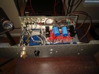
Here is a BA3 preamp that I built for an 82-year audiophile who can no longer solder.
The JFETs were acquired from Punkydawgs and the MOSFETs were acquired from a forum member.
The gain is just about exactly 10. undistorted pk-pk output output is about 30v.
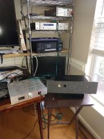
The second picture is the BA3 being listened to. The signal chain is
Television -> PL XA2.5 -> BA3 pre -> Zen V4 headphone amp -> headphones
Amazingly quiet having two unnecessary preamps in the chain. Sounds great.
I will be delivering the BA3 pre on Monday of next week.
We will listen to the BA3 through his Seas 3-way system that he built. He custom voices the crossover himself. He was a LEAP/LMS expert back in the day.
He designed all of NOVA USA's speakers back in the day. Picture of the big system attached. I listened to these and observed his work process. They were impressive.
The JFETs were acquired from Punkydawgs and the MOSFETs were acquired from a forum member.
The gain is just about exactly 10. undistorted pk-pk output output is about 30v.
The second picture is the BA3 being listened to. The signal chain is
Television -> PL XA2.5 -> BA3 pre -> Zen V4 headphone amp -> headphones
Amazingly quiet having two unnecessary preamps in the chain. Sounds great.
I will be delivering the BA3 pre on Monday of next week.
We will listen to the BA3 through his Seas 3-way system that he built. He custom voices the crossover himself. He was a LEAP/LMS expert back in the day.
He designed all of NOVA USA's speakers back in the day. Picture of the big system attached. I listened to these and observed his work process. They were impressive.
Attachments
Thank you Zen Mod...
The voltages across r10 and r11 are 1.2v each. I had these set to 1v but now, this morning, they are at 1.2v. I notice that this voltage varies with input signal.
r6 and r7 are at .81 volts each.
I will work on raising the resistance of r13...this must be part of the loading or degeneration that Nelson was talking about where gain is "thrown away" and a "tired puppy is a happy puppy"
Woofertester...I see those large heat sinks on the Mosfets...I've got to find some like that...will be interested to hear about the results of your listening tests when the time comes...
This BA-3 is intended for the 24v MOFO.
Thank you all...
then all is OK regarding currents through JFets and mosfets
for 24V MoFo , R13 ...... 430 or 470R
as I said, you must be sure is your problem not enough gain (for your expectations) or is it clipping
they are two different things ; gain issue is matter of setting (R13) while clipping is problem per se , fact that something is broken or simply wrong in circuit
and yes , you need some nice heatsinks on output mosfets
- Home
- Amplifiers
- Pass Labs
- BA-3 Amplifier illustrated build guide