Ferrofluid lasting 30 years?
In my experience with Audax tweeters, particularly the TWO25A1 (A TWO25A0 with added ferrofluid), then after 15 years or so the fluid has dried out a lot. I've converted more than one old TWO25A1 to the A0 version by laboriously cleaning the remains of the ferrofluid off the coil, and then using blotting paper and a fine needle to remove the rest out of the pole piece gap.
In my experience with Audax tweeters, particularly the TWO25A1 (A TWO25A0 with added ferrofluid), then after 15 years or so the fluid has dried out a lot. I've converted more than one old TWO25A1 to the A0 version by laboriously cleaning the remains of the ferrofluid off the coil, and then using blotting paper and a fine needle to remove the rest out of the pole piece gap.
Depends how hard the system is run. I've had to replace ferrofluid in three year old compression drivers.
The question was asked on another forum about ferrofluid. Read post 21.
It really all depends on the many factors involved.
ferrofluid cooled tweeters.... - Page 2 - AudioKarma.org Home Audio Stereo Discussion Forums
It really all depends on the many factors involved.
ferrofluid cooled tweeters.... - Page 2 - AudioKarma.org Home Audio Stereo Discussion Forums
Good evening!!
I'm back with some news.... 🙂

http://s13.postimage.org/8ohg4ubyv/2012_03_14_00_23_57.jpg
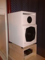
In few words, the sound is now far better than before: the xt19 is an awesome tweeter and with the BSC there is more punch from the SP1054. More detail, realism, better soundstage, flatter response and more natural sound than my previous setup.
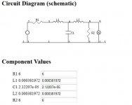
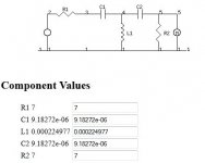
I had no time to tweak crossovers up to now. This is the actual circuit:
 The only thing I have done is to cut the port to have a tuning freq. of 45-50Hz.
This is the actual response, measured with emu 0204 and home made micro (the famous panasonic wm-61a):

woofer response:

tweeter response:
http://s16.postimage.org/jdsvvrnlh/tw_da_60cm.jpg

All the measurements have beend done in my room at a distance of 60cm (about 25 inch) on the tweeter axis.
What do you think about it?
I'm back with some news.... 🙂
http://s13.postimage.org/8ohg4ubyv/2012_03_14_00_23_57.jpg
In few words, the sound is now far better than before: the xt19 is an awesome tweeter and with the BSC there is more punch from the SP1054. More detail, realism, better soundstage, flatter response and more natural sound than my previous setup.
I had no time to tweak crossovers up to now. This is the actual circuit:
This is the actual response, measured with emu 0204 and home made micro (the famous panasonic wm-61a):
woofer response:
tweeter response:
http://s16.postimage.org/jdsvvrnlh/tw_da_60cm.jpg
All the measurements have beend done in my room at a distance of 60cm (about 25 inch) on the tweeter axis.
What do you think about it?
...snip...
What do you think about it?
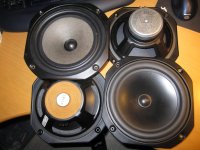
Amazing, Michelino! So impressed! Just to remind everyone. Michelino is using the ancient KEF B200 SP1054 plastic 8" bass/mid in a smallish reflex box around 28L with the 4 ohm Vifa XT19 tweeter that everyone likes so much:
Vas 130L
Qm 3.27
Qe 0.25
Qts 0.23
Le 0.45mH
Re 7.0R
Fs 25Hz
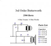
Effective 3rd. order crossover around 2.5kHz, because he's using the 0.45mH woofer inductance as the second crossover coil element and the bafflestep resistance modifies the coil and capacitor values as below. 😎
LC Filter Design
The KEF takes advantage of better modern tweeters and a lower crossover point! Plus some time delay compensation...the icing on the cake! Very well done, my friend. A minor masterpiece. 😀
Last edited:
Really love the time delay design, they remind me of the classic Leaks from the 70's (always wanted a pair) but I'm being dead thick here what's the circuit design of? I can't make head nor tail of it!
All the best
All the best
Really love the time delay design, they remind me of the classic Leaks from the 70's (always wanted a pair) but I'm being dead thick here what's the circuit design of? I can't make head nor tail of it!
All the best
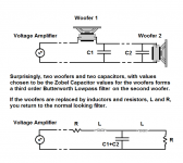
It's the lowpass circuit which is, IMO, clever. It uses a RL Bafflestep Compensation Circuit as an input resistance.
This gives you a 3rd. order 2500Hz Butterworth on the bass/mid in effect, but the component values get modified so the coils are the same size:
An externally hosted image should be here but it was not working when we last tested it.
LC Filter Design
This is different from the standard calculation:
2-Way Crossover Designer / Calculator
[URL="
An externally hosted image should be here but it was not working when we last tested it.
Butterworth filters have a pleasingly flat impedance, and the input resistance should give a valvey sound and an easy load.
Attachments
Good morning and Good Easter!
Yeah, I'm satisfied about my new speakers, Steve 🙂 ... Thankyou so much!
But, I'm not so expert so tell me... what did I do of so special? I've played with LSPCAD and then realized the design... The high pass is a Butterworth filter @2,8kHz, the lowpass even a butterworth but with the BSC.... Then 20mm of buffle thickness and that is 🙂 ...
...
..
.
Ok, I've undestood. That's a trick in that LC filter calculation you suggested... but I've not undestood what is that trick 🙂 ... are there some more infos on the web?
Last 2 things: 28liters of box is not enough. 80Hz of -3dB frequency is not enough I think. And... The about XT19 resoponse... How can I make it flatter?
Good afternoon, my friend. Christ has risen a little later in Portsmouth. 🙂
What you've done is apply an elegant result which fits a filter exactly to a particular bass unit. Here, a B200 SP1054 with a Re of 7 ohms, Le 0.45mH.
Applying Le/Cz=49 (Re squared), we get a Zobel capacitor of 9.187uF. This in series with 7 ohms will theoretically flatten the impedance of the bass unit, but we're not doing that. It just remains to calculate the resonant frequency for those values of Le and Cz and 14 ohms as a series LCR circuit, which here is 2476 Hz.
Alan Yates' Laboratory - VK2ZAY's Engineering Calculators - LCR Resonance
It's my notion that it is a VERY GOOD THING to use matched source/load filters with transistor amplifiers, because they have very nice impedance which should give a warm sound equivalent to valve amplification.
LC Filter Design
You now can use the bass unit's voicecoil inductance as a filter component, the 7 ohm input resistor in parallel with a coil to do 6dB bafflestep correction, and it all works out well. To be fussy, you should do the same with the highpass tweeter filter, which will flatten overall impedance, but I'll forgive you here. 😉
To boost bass, you could modify your R1 value to 7 ohms. I would L-pad the tweeter too, to get it to roughly 7 ohms. The Vifa XT19 is an uncomfortably low 2.9 ohms Re, and that really needs raising. To consider for your next effort anyway! 😎
What you've done is apply an elegant result which fits a filter exactly to a particular bass unit. Here, a B200 SP1054 with a Re of 7 ohms, Le 0.45mH.
An externally hosted image should be here but it was not working when we last tested it.
Applying Le/Cz=49 (Re squared), we get a Zobel capacitor of 9.187uF. This in series with 7 ohms will theoretically flatten the impedance of the bass unit, but we're not doing that. It just remains to calculate the resonant frequency for those values of Le and Cz and 14 ohms as a series LCR circuit, which here is 2476 Hz.
Alan Yates' Laboratory - VK2ZAY's Engineering Calculators - LCR Resonance
It's my notion that it is a VERY GOOD THING to use matched source/load filters with transistor amplifiers, because they have very nice impedance which should give a warm sound equivalent to valve amplification.
LC Filter Design
You now can use the bass unit's voicecoil inductance as a filter component, the 7 ohm input resistor in parallel with a coil to do 6dB bafflestep correction, and it all works out well. To be fussy, you should do the same with the highpass tweeter filter, which will flatten overall impedance, but I'll forgive you here. 😉
To boost bass, you could modify your R1 value to 7 ohms. I would L-pad the tweeter too, to get it to roughly 7 ohms. The Vifa XT19 is an uncomfortably low 2.9 ohms Re, and that really needs raising. To consider for your next effort anyway! 😎
Attachments

Thiele Small parameters
Old thread ... but I'll try anyway 🙂
Just got myself the bass drivers from a Cara ... all 4 units for less than 15 Euro!!
Couldn´t resist the offer 😀
Does anyone have some Thiele Small parameters for these??
Bass SP-1193 and Passive SP-1185
Was thinking of making a small sub for my PC or something, maybe using the two active woofers in iso-baric and adding some weight to the passive to lower resonance ......
Thanks in advance Baldin 🙂
Hi Sure I came across this sp 1193 drivers. I have KEF CARA 1985 2-way speaker which I would like to MODIFY to better sounding speakers wit the tweeter and Mid/Bass drivers preserved.
Old thread ... but I'll try anyway 🙂
Just got myself the bass drivers from a Cara ... all 4 units for less than 15 Euro!!
Couldn´t resist the offer 😀
Does anyone have some Thiele Small parameters for these??
Bass SP-1193 and Passive SP-1185
Was thinking of making a small sub for my PC or something, maybe using the two active woofers in iso-baric and adding some weight to the passive to lower resonance ......
Thanks in advance Baldin 🙂
Attachments
Last edited:
Hi all
I need the specs of KEF Type SP1092 speaker coming from CODA III B200 unit. Actually I am looking for replacement as the coil started rubbing the magnet. Except of that speakers sound still great at high levels. Wondering what could be a cause... maybe rust (?)
Many thanks
Raf
I need the specs of KEF Type SP1092 speaker coming from CODA III B200 unit. Actually I am looking for replacement as the coil started rubbing the magnet. Except of that speakers sound still great at high levels. Wondering what could be a cause... maybe rust (?)
Many thanks
Raf
Take out the offending bass unit, mark the upside of the magnet with an indelible marker, then turn it 90 degrees. Usually fixes it. The spider and surround sags, I expect.
I don't know for sure who made the paper bass, possibly Elac, but it's a common model found in a lot of old designs. Like the Monitor Audio R352.
I'd think this will work well enough as a replacement:
80W 8in Shielded Bass Mid Range Speaker | Maplin
I'd need to see the crossover to suggest any more. But you can adjust tweeter level with a ceramic resistor or two.
- Status
- Not open for further replies.
- Home
- Loudspeakers
- Multi-Way
- B200 Kef Drivers