I would re-solder the right and left output grounds and positives, the right and left input grounds and then retry T7 & 8 measurements.
I'm going to try to rule out the obvious: do you mean that T7 can't go lower than 14.5V? Or do you mean that if you "match" the position of both the trimmers, you get mismatched results? If that's the case, don't worry about matching the position of the trim pots, just turn them as much or as little as you need, even asymmetrically...the important is thing is that the values matchHi everyone, sorry I have to bother you guys with a problem I am having. I just build the Korg B1 with the JFET set from the diyaudio store. Everything went fine, Voltages T1 to T6 all check out perfectly. T8 is also adjusting fine.
T7 however, I cant get the bias to go any lower than 14.3V. The left tube is visible brighter as well, accordingly.
I checked all the resistors before putting them in, and after again. Caps are all oriented correctly.
I changed out the left pot and the 10uF cap next to it, to no avail.
Going through the above posts, the Voltages across the R1 resistors all check out symmetrically. The 33.2K resistors differ in their voltage drop, but that is down to the pot adjustment, right... I can adjust the pot to match the the right channel, and the pots end up in roughly the same position. However T7 is 14.57V while T8 is 9.49V.
Any hints as to what might be the problem? could it be the nutube? Or could there be a transistor problem? Thank you so much, I don't have much of an electronics background, and this is my second project (after an ANK Dac many years ago). I am at a loss here... 🙁
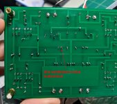
I’d start with reflowing suspicious-looking JFET legs on the problem chan. Then clean the greasy flux off the board, with specific focus on JFET legs. Culprit might be there, low currents through JFETs make them susceptible to erratic behaviour due to flux residue between legs. JFETs are wonderful for audio, not as suitable for kama sutra.Hey Dirk, yeah I am sure. I measured the resistors with a multimeter 😬 thank you anyways. I'll post a photo of the bottom as well..
same goes for Nutube.
if this does not solve it, interpret colour scheme of all resistors. Not easy to measure exactly when in-circuit. Also check resistor solder joints.
edited to add: I posted before seeing the back of the board. Agree with elwood, those joints are cold. I also see some burnt traces/joints. I would clean and reflow them.
a tip: flux is nice, but a deoxidised and clean solder tip is just as important for heat transfer.
Regards,
Andy
Last edited:

Good point. However, given matched active devices and close tolerances of passive components, in my build I found that relative equality of pot positioning is indicative of a succesful build. And, if he adjusts for 14-ish volts at the approx 3 o’clock position, I doubt he can reach 9V5 within the pots range.I'm going to try to rule out the obvious: do you mean that T7 can't go lower than 14.5V? Or do you mean that if you "match" the position of both the trimmers, you get mismatched results? If that's the case, don't worry about matching the position of the trim pots, just turn them as much or as little as you need, even asymmetrically...the important is thing is that the values match
Regards,
Andy
Hey, thank you all for the input.
I went through everything - and yes, I mean that T7 can not go lower than 14.3V no matter what.
Resoldered the inputs and outputs, same result
Resoldered the jfets and nutube, cleaned all the flux, still exactly the same problem.
But thank you Andy for the colorful analogy. I will keep that in mind for sure 😀 erratic behaviour due to flux between the legs... ^^
I will post a picture of the board from my phone. Thank you all. I might order a second nutube and see whether it's down to the tube. And on to the F5 in the meantime..
I will keep in mind to work cleanly next time around... Just to safe myself the embarrassment if i have to ask for help and show the work.. 😉
Test the operability of the trim-pot in question? Ohm-meter on center and each leg in turn, and see if it's doing its job when adjusting it.
If it's doing its job, you might re-flow it as well.
You might check the flow on the 33.2 resistors and caps right between the pots and the tube as well.
If it's doing its job, you might re-flow it as well.
You might check the flow on the 33.2 resistors and caps right between the pots and the tube as well.
Thanks, i changed the pot already (working in principle) and changed that cap as well (which is why the joint looks a bit suspicious @Dirk).Test the operability of the trim-pot in question? Ohm-meter on center and each leg in turn, and see if it's doing its job when adjusting it.
If it's doing its job, you might re-flow it as well.
You might check the flow on the 33.2 resistors and caps right between the pots and the tube as well.
I just redid the pot and cap and 33.2k resistor joints, end result is still the same however.
Frontpic is on the previous page, @ClaudeG.
Thanks to everyone for the input.
Seems to me like all the voltages going into the nutube are correct, coming out is too high a voltage at t7?
Last edited:
R1 varies with the Jfets and are matched and packaged with them. That’s why they are “R1” and not a given value.
Looking at the photos I’d guess R R Br Bl Br for 221R…. ?
Looking at the photos I’d guess R R Br Bl Br for 221R…. ?
I know you know, but spelled it out for those who may not. 🙂
It’s likely a bad solderjoint somewhere, as always, it’s poking bad measuring until it’s found.
It’s likely a bad solderjoint somewhere, as always, it’s poking bad measuring until it’s found.
I’d perform those measurements Ben suggests.Thanks, i changed the pot already (working in principle) and changed that cap as well (which is why the joint looks a bit suspicious @Dirk).
I just redid the pot and cap and 33.2k resistor joints, end result is still the same however.
Frontpic is on the previous page, @ClaudeG.
Thanks to everyone for the input.
Seems to me like all the voltages going into the nutube are correct, coming out is too high a voltage at t7?
Also, in my amateuric approach to things, I would perhaps have measured voltages between JFET legs, to see how much they differ from fet to fet. Meaning a DMM with one probe on for example drain leg, and one on the source leg. My ignorance to circuit understanding is apparent, but through this approach I once troubleshooted a voltage-spiked ACP+ J74 and fixed it in an hour. Goal being more important than means, it can’t hurt 🙂
dunno, but Ben: if one of two JFETs in a channel is shot, could that explain his issues?
If Ben sez not, plz disregard 🙂
regards,
Andy
Last edited:
Could be JFET, could be NuTube, could be bad joint. The intent is to try see what current is flowing through the NuTube and JFETs, to possibly figure out where the problem lies.
Hi Ben, thank you for your insight. However, don't quote me on the color codes, given my deuteranopsia...A few voltages across resistors may aid in diagnosis:
View attachment 1030644
What is the value of R1? I am having a hard time identifying the colours. They look like brown brown green black (115R) but I am not sure.
R1 measures around 119,5 Ohms on the top left+right, 123 Ohms on the bottom left+right.
As to the voltages:
R1 top left: 1.61
R1 top right: 1.61
332k left: 7 (with the pot turn max clockwise -- if i turn the pot anticlockwise, the voltage across goes down)
332 right: 11.45
475 left: 8.32
475 right: 8.32
jfets measured from drain to source:
Q1 left: 6.85
Q1 right: 11.5
Q2 left: 12.6
Q2 right: 7.9
Thanks again to everyone, so much appreciated 🙏
The JFETs look good.
The NuTube left channel is not drawing enough current. So it is either faulty, the bias supply to the grid is faulty, or bad solder joints in the area.
What is the voltage at the NuTube grid (marked "G1" and "G2", left and right) relative to ground?
The NuTube left channel is not drawing enough current. So it is either faulty, the bias supply to the grid is faulty, or bad solder joints in the area.
What is the voltage at the NuTube grid (marked "G1" and "G2", left and right) relative to ground?
The JFETs look good.
The NuTube left channel is not drawing enough current. So it is either faulty, the bias supply to the grid is faulty, or bad solder joints in the area.
What is the voltage at the NuTube grid (marked "G1" and "G2", left and right) relative to ground?
G1 is 2.91V
G2 is 2.46V
🤔

- Home
- Amplifiers
- Pass Labs
- B1 with Korg Triode