..The hole on print is 10mm center center. the caps 12-12,5mm.
Bend both 1.25mm horizontaly in the cap center direction then verticaly "shape L" for 10 mm pitch
..but looks promising!
Learn with patience is a Diyer treausure..
Biger joy if all work perfectly finnaly 😀 Have a nice day
Maybe change for new diode
Yup. It looks like the filament has gone.
Is there any reason this may have happened or just bad luck? The voltages checked out okay when I originally set it up. The T6 reading of 0.719v is much higher following the loss of the left channel.
Is there any reason this may have happened or just bad luck? The voltages checked out okay when I originally set it up. The T6 reading of 0.719v is much higher following the loss of the left channel.
Attachments
Last edited:
I finished the Kb1 from the full kit and following the guide and all sounds good. Less a testament to my skills than all those putting together the kit and the information...and the designer - Thanks!
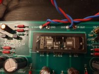
I mounted the Nutube on the double sided sticky foam pad.
Having watched a YT video (a source I trust implicitly) it was said not to cover the circle on the back of the Nutube - the 'exhaust seal cap' - no one likes a blocked exhaust right, but should I be concerned and interrupt the music to dive back in?
if you have poof from that exhaust, that means vacuum is exausted, and air is inhousted 
so, do what you wish with exhaust, just to not open it 🙂
so, do what you wish with exhaust, just to not open it 🙂
Having watched a YT video (a source I trust implicitly) it was said not to cover the circle on the back of the Nutube - the 'exhaust seal cap' - no one likes a blocked exhaust right, but should I be concerned and interrupt the music to dive back in?
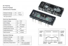
Data sheet translation is from Japanese as "exhaust port". This is a misnomer. It is a vacuum port which is sealed at factory after creating the vacuum and nothing should ever leave or enter the tube after sealing. Covering the port should not be an issue.
Is there any reason this may have happened or just bad luck?
Nutube filament current = 17mA
max filament voltage = 0.8V
I always take care to touch with finger jets plastic package only..
Korg easily can be mechanically damaged if....
Ooops is on the concrete floor now

 😉 falling down from the work bench for example
Attachments
It lives! And never a sore heel ahead.
Always good advice to be patient! Finished primary build last night and see two nice little glowing eyes looking back at me. Awesome. Just too cool after having messed with fire bottles for a few decades.
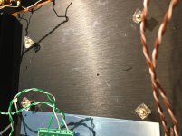
I gave the teaser the other day on board insulation for microphonic reduction. See photos - bought a firm but squishy (contrarian?) heel pad and chopped some small pieces to sit on the stand offs. Not too tight on the bolts and voila, a little bit springy. Reminds me of my Dual plinth!
Fussed more with the diode and gave up for now. Heck, Poppa says run it "on" all the time so maybe lack of power light will not bother me (unlikely).
Next question for the group - testing the biasing pots. I know I have to hit TPs 7 & 8. Are the test leads clipped to both simultaneous or red to TP and black elsewhere like ground? I'm guessing red to TP and black to chassis like biasing my Dynas to 1.56.
DIY learner everyday but you won't have to tell me twice...🙂
Always good advice to be patient! Finished primary build last night and see two nice little glowing eyes looking back at me. Awesome. Just too cool after having messed with fire bottles for a few decades.
I gave the teaser the other day on board insulation for microphonic reduction. See photos - bought a firm but squishy (contrarian?) heel pad and chopped some small pieces to sit on the stand offs. Not too tight on the bolts and voila, a little bit springy. Reminds me of my Dual plinth!
Fussed more with the diode and gave up for now. Heck, Poppa says run it "on" all the time so maybe lack of power light will not bother me (unlikely).
Next question for the group - testing the biasing pots. I know I have to hit TPs 7 & 8. Are the test leads clipped to both simultaneous or red to TP and black elsewhere like ground? I'm guessing red to TP and black to chassis like biasing my Dynas to 1.56.
DIY learner everyday but you won't have to tell me twice...🙂
Attachments

Last edited:
Always good advice to be patient! Finished primary build last night and see two nice little glowing eyes looking back at me. Awesome. Just too cool after having messed with fire bottles for a few decades.
I gave the teaser the other day on board insulation for microphonic reduction. See photos - bought a firm but squishy (contrarian?) heel pad and chopped some small pieces to sit on the stand offs. Not too tight on the bolts and voila, a little bit springy. Reminds me of my Dual plinth!
Fussed more with the diode and gave up for now. Heck, Poppa says run it "on" all the time so maybe lack of power light will not bother me (unlikely).
Next question for the group - testing the biasing pots. I know I have to hit TPs 7 & 8. Are the test leads clipped to both simultaneous or red to TP and black elsewhere like ground? I'm guessing red to TP and black to chassis like biasing my Dynas to 1.56.
DIY learner everyday but you won't have to tell me twice...🙂
Not simultaneus..
Check the value after ~15 minutes of warming.
TP 7 one point with red lead cable, black to ground if after adjustement voltage value is OK ..then go next TP 8.
Thanks, Soundhappy! Appreciate you being at the ready with answers the past couple of weeks. Or as it appears, Merci!
Based on your profile, you might appreciate this goes into my Class A system powering 8" Audax full-rangers in my kit speakers! Sing like Angels, indeed.
Based on your profile, you might appreciate this goes into my Class A system powering 8" Audax full-rangers in my kit speakers! Sing like Angels, indeed.
Last edited:

 Congratulations
Hi Soundhappy,
As I always promised my parents, all proper precautions were employed. The Nutube stayed in its box until required and I always assemble my projects on ESD matting with a earthing wrist strap attached. It had been working absolutely fine for over a week before this happened and all voltages were correct.
I'll order up another Nutube from RS later.
Just a thought, could my incorrectly inserted capacitor on the the right channel the week before somehow have led to inappropriate amperage to the filament wire on the left leading to its early demise?
Hi SupperReady
Great🙂 Work with good tools = less bad surprises.
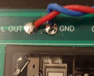
On the left side do you have some GND piece of wire floting who can make short contact with L output positive ?
Filament current was probably too much..
Something useful How To Clean Printed Circuit Boards - YouTube
Great🙂 Work with good tools = less bad surprises.
On the left side do you have some GND piece of wire floting who can make short contact with L output positive ?
Filament current was probably too much..
Something useful How To Clean Printed Circuit Boards - YouTube
Attachments
Hi Soundhappy,
As I always promised my parents, all proper precautions were employed. The Nutube stayed in its box until required and I always assemble my projects on ESD matting with a earthing wrist strap attached. It had been working absolutely fine for over a week before this happened and all voltages were correct.
I'll order up another Nutube from RS later.
Just a thought, could my incorrectly inserted capacitor on the the right channel the week before somehow have led to inappropriate amperage to the filament wire on the left leading to its early demise?
I don't see how the decoupling cap or shorted output can cause the Nutube filament to burn out. You may have a defective Nutube or somehow you had a short across the 475 ohm resistor that goes before the filament.
Continuity tests is my favorite, specially on pcb traces with jfets, triode and big filtering capacitors joints etc. 🙂
Quick and simple , make me feel relaxed : no short contacts or cold joints.
Better sleep after work on the bench
Quick and simple , make me feel relaxed : no short contacts or cold joints.
Better sleep after work on the bench
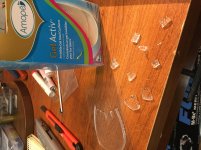
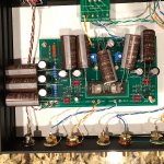
Capacitor Physical Size
Well, I ordered Elna Silmic II caps to replace the supplied caps in the signal path of the B1 and that won’t be a problem. I figured as long as I was ordering I’d also replace the 1,000uF caps with Silmics. I didn’t pay much attention to the size and expected them to be only somewhat larger. Well, they’re huge. The only way I see for them to fit it to mount them above the board and lay them over horizontally as roughly indicated in the photo. I sure need advice as to whether I should proceed or if there is an alternative. Thanks for any help.
Well, I ordered Elna Silmic II caps to replace the supplied caps in the signal path of the B1 and that won’t be a problem. I figured as long as I was ordering I’d also replace the 1,000uF caps with Silmics. I didn’t pay much attention to the size and expected them to be only somewhat larger. Well, they’re huge. The only way I see for them to fit it to mount them above the board and lay them over horizontally as roughly indicated in the photo. I sure need advice as to whether I should proceed or if there is an alternative. Thanks for any help.
Attachments
I got some Silmics for a Whammy and had a similar problem: The leads are too far apart, and they don't really fit. They are big, those things. That'll teach me to look more closely at the specs!
- Home
- Amplifiers
- Pass Labs
- B1 with Korg Triode