Oh. My. That sounds verrrrrrrrrrrrrry nice. I know I'll eventually want to run it through a distortion analyzer ( dont have one yet ), but I am more than happy with how it sounds now. And could be content with it as such for a very long time. Still more than enough gain with my vfet amp.
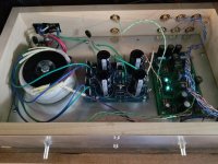
For the pics or it didn't happen crowd:
For the pics or it didn't happen crowd:
Attachments
Could you tell us Some more About the sound? Soundstage, detail etc?
Looks like a very nice project to build when pcb's come available!
Looks like a very nice project to build when pcb's come available!
Congrats to delecoy!
BK
Thank you! And many thanks to you again, for your contribution. 🙂
As for the sound...very detailed. Points of reference are a DCB1 and a BA3-FE. Given the many ways to build those, dial them in, and pair them up - I will not say better or worse. Too many variables. But I will say, in my system, it yields the detail of the DCB1 with the warmth of the BA3-FE. Which I like. A lot. My speakers are terribly positioned ( for bass response, at least ) but don't have any close walls to the side so tend to throw a good sound stage unless something is wrong. They're pulling the full disappearing act right now. As with all combos that dredge a lot of detail: GIGO. But throw it a nice track from a good source and you will be rewarded. Very.
Its also been playing cartoons half the day, with aplomb 😀
Attachments

Need a bit of help,
I'm just about done stuffing the board but can't figure out the exact placement of the capacitors. I'm not smart enough yet to read the schematic....
Here is a picture with each capacitor labeled C1 to C8.
Can someone help me fill in the blanks or correct my mistakes?
C1
C2
C3 - 1000
C4
C5
C6 - 2200
C7 - 2200
C8 - 2200
The BOM's listed 4 2200 caps and 4 1000 caps so it has me thrown off.
Thank you !
Kevin
Attachments

I believe NP's updated schematic stated that ALL those particular caps C1-8 on the Christmas board are 1000 microfarad, but larger values to 2200 for the C6-8 are OK. The original circuit diagram cited some 2200 caps, but the specs were modified for the newer board.
Regarding the 10uF output cap, if you hang this output to a power amp with 10 kOhms input impedance your -3dB will be 1.6 Hz. 10k will be dominant to the 221k or 332k output resistor to ground.
Another topic. I guess NP has all he can desire. But nevertheless this group should find something for him. I propose the ones who think this is a good idea goes to the local record shop or flea market or whatever, and sniff up some native CD or LP and send it to him. Some recordings you belive he does not have, and that you think he will enjoy.
He has given us so much, and probably he gets some ideas and fun in return, but, anyway, just what I though was a good idea.
I believe NP's updated schematic stated that ALL those particular caps C1-8 on the Christmas board are 1000 microfarad, but larger values to 2200 for the C6-8 are OK. The original circuit diagram cited some 2200 caps, but the specs were modified for the newer board.
I like big capacitors for supply filters, but I have to balance this against
the wall-wart supply characteristics. Numerous of those will not charge
the large caps because their protection circuits trigger on the high inrush
at turn-on, even through they are more than adequate at steady state.
The first 10 ohm resistor in the filter should limit the inrush current to max. 2.4A for a 24V supply? …..then the 24V/5A Meanwell SMPS that replaced the smaller 19V supply should be able to handle the inrush even with 2200 uF caps?
Depends on the supply. Some of these appear to sample the load at lower voltage,
and if they see current presume that it will be lots more at higher voltage.
and if they see current presume that it will be lots more at higher voltage.
Board and JFETs arrived today. Just want to take this opportunity to thank Nelson, qwertyl, Soundhappy and anyone else who has helped make this happen.
I'm new to this hobby, Pete Millet's Nutube buffer was my first build, and excited about getting stuck in and seeing what Nelson's circuit can do.
I'm new to this hobby, Pete Millet's Nutube buffer was my first build, and excited about getting stuck in and seeing what Nelson's circuit can do.
Mine landed today... As per previous posts a heart felt thanks to Mr Pass and those who made this an effortless pleasure on my behalf.
I’m very great full to you all...
Thanks
I’m very great full to you all...
Thanks
Same here - I got mine today also 🙂 Thanks to Mr Pass for your time and generosity along with all the DiyAudio helpers!! I am very grateful and looking forward to working on this project!
I am curious. Nelson, what gauge and type (solid/stranded) hookup wire do you use in First Watt and Pass pre-amps and amps? Teflon?
- Home
- Amplifiers
- Pass Labs
- B1 with Korg Triode