Can we see pictures of the back of your board?
Sure can, I will have to send them in the morning, as I am home now and my hobby (obsession) shop is 45 minutes away! It will be a fruitless endeavor though, I checked all traces and connections with the schematic, solder joints are good, I checked with high magnification, I may have just gotten a 6p1 with a small vacuum leak which led to its early demise. It was handled with anti static protocol on my end.
You're confident that your solder joints and component values are good so how about focus on the voltages present.
Print a copy of your schematic and work your way around, annotating the schematic with the voltage values you find then upload a copy here. That will be very helpful in identifying what component may be at fault.
Print a copy of your schematic and work your way around, annotating the schematic with the voltage values you find then upload a copy here. That will be very helpful in identifying what component may be at fault.
T1-T6 are spot on Nelson’s calculations, the circuit biased perfectly and I was able to set T7 and T8 to 9.5 volts, until one channel failed entirely, follwed by the second channel. All published test points were achieved. All test points are still good except T7 and T8, which are at 12v and .5 v.
The schematic is from Nelson using the board V1R1, with the Diy store’s Board and J113 jfets. All voltages T1-T8 were perfect. T7 and T8 are now at 12v and .5 respectively. I also used Nelson’s suggested BOM from digi-key. I think it’s likely a faulty 6P1, Nelson’s bias circuitry is spot on, both channels initially worked, one developed a static style noise and failed, the other played perfectly and then failed. 😕
The schematic is from Nelson using the board V1R1, with the Diy store’s Board and J113 jfets. All voltages T1-T8 were perfect. T7 and T8 are now at 12v and .5 respectively. I also used Nelson’s suggested BOM from digi-key. I think it’s likely a faulty 6P1, Nelson’s bias circuitry is spot on, both channels initially worked, one developed a static style noise and failed, the other played perfectly and then failed. 😕
The test points are calibration points for a healthy circuit. To identify an issue, you need to look deeper. For example, you have the voltages at TP7,8 but what is happening either side of Q1, Q2? What is pulling your voltage down to 0.5?
If you are confident with desoldering, pull the nutube back out and again measure the circuit voltages. This is where a before/after comparison of circuit voltages helps.
You can either confirm empirically that the nutube is the likely fault source, or you could always blindly put another in and hope it lasts longer this time. Your $$ but I personally prefer to be certain before blowing another $50+ component.
If you read my previous posts I have empirically confirmed T1-T6 operates as normal, T7-T8 measured perfectly, those points failed slowly, if you understand the circuit the problem is already narrowed, empirically speaking. T1-T6 continue to measure perfectly.The test points are calibration points for a healthy circuit. To identify an issue, you need to look deeper. For example, you have the voltages at TP7,8 but what is happening either side of Q1, Q2? What is pulling your voltage down to 0.5?
If you are confident with desoldering, pull the nutube back out and again measure the circuit voltages. This is where a before/after comparison of circuit voltages helps.
You can either confirm empirically that the nutube is the likely fault source, or you could always blindly put another in and hope it lasts longer this time. Your $$ but I personally prefer to be certain before blowing another $50+ component.
If T5 and 6 are at the correct voltage, then the heaters have not
been damaged, otherwise they would show higher voltage.
I do not recall you mentioning what voltages you are getting at T7 and 8.
been damaged, otherwise they would show higher voltage.
I do not recall you mentioning what voltages you are getting at T7 and 8.
If T5 and 6 are at the correct voltage, then the heaters have not
been damaged, otherwise they would show higher voltage.
I do not recall you mentioning what voltages you are getting at T7 and 8.
T7 Measures 1.806v
T8 Measures 2.588
If T5 and 6 are at the correct voltage, then the heaters have not
been damaged, otherwise they would show higher voltage.
I do not recall you mentioning what voltages you are getting at T7 and 8.
T5 Measures .6mv
T6 Measures .613 mv
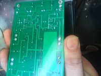
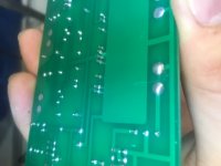
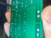
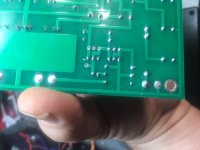
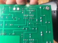
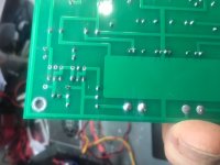
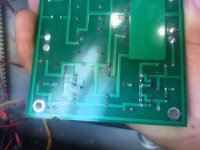
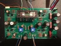
Can we see pictures of the back of your board?
Back of board pictures per your request.
Attachments

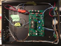
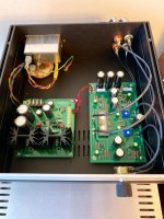
Hello All, I finally had a chance to assemble my B1 Nutube and get it in a chassis. I repurposed the chassis I'd used for my B1 buffer and just added a power switch. In an effort to tame the microphonic issue that's been reported I used silicone PC fan mounts with two sided tape to keep them still. I also soldered wire leads to the Nutube to try and dampen any direct vibration as others have done. Being a rookie I made the leads a little short which made getting the leads soldered into the pcb a near headbanging experience. I would recommend that anyone going this route make the leads longer to provide more flexibility to solder the wires in. There is the "tinging bell" microphonic sound that has been reported, but only when I turn the input knob. To be honest its no where as loud or intrusive as I thought it would be, and fades quickly. All of my initial measurements were within 0.5 volts as described in Nelson's Nutube PDF, and I adjusted the pots to 9.6v to start. I've been listening to it along with my M2x for almost two days and all seems ok. I'll play around with the pots settings after my current setting has sunk in a little.
A huge thank you to Nelson for creating this project, and to the DiyStore for getting it out for everyone to buy. The quick build guide that 6L6 put together in the thread is as always very helpful, thanks Jim!
A huge thank you to Nelson for creating this project, and to the DiyStore for getting it out for everyone to buy. The quick build guide that 6L6 put together in the thread is as always very helpful, thanks Jim!
Attachments

T7 Measures 1.806v
T8 Measures 2.588
That might explain why you think the tube is blown - I have noted that
it doesn't glow with no voltage on the Plate.
I suggest you remove the output buffer fet Q1and see what happens to
the Plate voltage - you can measure it at its 1K gate resistor.
Also when you do that, note if the cathode is glowing blue.
Thanks Nelson, I will give that a shot, thanks!
Nice! I am jealous!!
Don’t give up!! Nelson and the other amazing members of this forum will help you or anyone willing to try and take advice to make it work. The Diy Audio site is a great place, whether you’re a novice or a seasoned professional.

Thanks Nelson, I will give that a shot, thanks!
See what I mean? 😉
Another one comes to life. Galaxy case, 10k stepped attenuator, AMB s11 supply. This is from the xmas batch - thanks Papa!
BK
Clean build bk, well done!
- Home
- Amplifiers
- Pass Labs
- B1 with Korg Triode