SRPP...….A Shunt Regulated…….something? …….PP is not Push Pull?
I was just looking at the 50k input pot......if I should get a conventional stepped serial attenuator or a shunt type...….
I was just looking at the 50k input pot......if I should get a conventional stepped serial attenuator or a shunt type...….
Oh I see two Korg's for mono SRPP channel ?
It looks fun with the two windows to watch the blue light of the tubes...….will see what DIY store finds out regarding chassis...….. 🙂
http://www.tubecad.com/articles_2002/SRPP_Deconstructed/SRPP_Deconstructed.pdfSRPP...….A Shunt Regulated…….something? …….PP is not Push Pull?
I am attempting to have focus on one thing at a time.
It's not easy.
At the moment there are about 15 things on the list.
I am greedy too but Papa would not like it if we are also lazy..
It think I have to DIY with the given circuit. I appreciate it enough already.

I'm in too!
I looked for the 2SK370's but haven't had any luck. I've read that they where replacements for 2SK170's. Those I can find. If they work, do they need to be matched?
I looked for the 2SK370's but haven't had any luck. I've read that they where replacements for 2SK170's. Those I can find. If they work, do they need to be matched?
6P1 question:
Dear all,
According to the spec, 6P1 has a common cathode formed by 2 filaments and connected As F1 - F2 (common) - F3
It means that the Korg can’t be used as separate triodes.
If you do have a specimen, please have a look, is there any bridging in between ?
Pin 1-2
Pin 16-17
Such as small metal tab between those pins.
If it does, may be if those links been cut, we may have two separate triodes.
Thanks
Pascal
Attachments
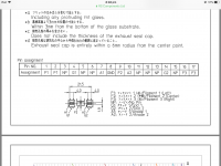
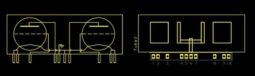
Here is the pin diagram, reference triode #1 and #2
1 filament 1
2 filament 1
4 grid 1
7 anode 1
8 ground (not attached to triode circuits)
9 filament center - common to both triodes
10 anode 2
14 grid 2
16 filament 2
17 filament 2
The one pin in common to both triodes attaches to both filaments.
The rest of the pins are named after me.
🙂
1 filament 1
2 filament 1
4 grid 1
7 anode 1
8 ground (not attached to triode circuits)
9 filament center - common to both triodes
10 anode 2
14 grid 2
16 filament 2
17 filament 2
The one pin in common to both triodes attaches to both filaments.
The rest of the pins are named after me.
🙂
Thank you Mr Pass,
Definitely must have two 6P1 for an SRPP circuit.
All neutered by Korg, poor Nelson
Definitely must have two 6P1 for an SRPP circuit.
All neutered by Korg, poor Nelson
The rest of the pins are named after me.
🙂
Thanks Mr Pass !Here is the pin diagram, reference triode #1 and #2
1 filament 1
2 filament 1
4 grid 1
7 anode 1
8 ground (not attached to triode circuits)
9 filament center - common to both triodes
10 anode 2
14 grid 2
16 filament 2
17 filament 2
The one pin in common to both triodes attaches to both filaments.
I see better now.
Direct heated triode filament 1&2 = cathode 1&2
Attachments

Voltage swing
Question
What are the possibilities to increase voltage swing?
Plate choke would be great but with a Rp of 300k Ohm for the korg triode a crazy undertaking.
At the same time there are chokes made by SACTHAILAND with 7400 Henries which makes a -3db point at 10 hz possible
Those are grid chokes but the tiny current of the tube could allow for their use....?
The voltage gain and swing characteristics for the Nutube circuit that I
used were the load-line that I preferred. You can get more or less gain
and more or less distortion by playing with the loading and bias figures,
but it becomes a different animal (one that you might prefer).
If you want to increase the voltage swing I suggest a gain stage after
the Nutube, and while you're at it, you might want to make it inverting,
as that Nutube circuit inverts phase and requires another phase inversion
after it to get the whole thing right. Previously I have just inverted phase
at the speaker when using it.
The voltage gain and swing characteristics for the Nutube circuit that I
used were the load-line that I preferred. You can get more or less gain
and more or less distortion by playing with the ....
Thank you Nelson for your valuable comment. You most probably allready exploited the full potential of this triode.
best regards
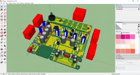
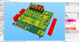
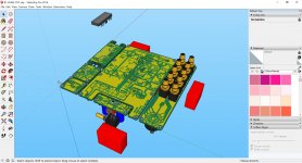
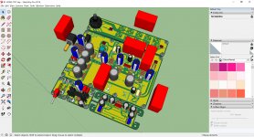
Modifications done.
TKD 2CP601 or ALPS RK09 potentiometer.
Added capacitor multiplier.
I´m working on the part list.
JP
TKD 2CP601 or ALPS RK09 potentiometer.
Added capacitor multiplier.
I´m working on the part list.
JP
Attachments
It might be too late, but since you mounted the Nutube in a daughter board, you could have the flatcable connector on the bottom of the board so one could mount the board showing the tube in a window on the case.
- Home
- Amplifiers
- Pass Labs
- B1 with Korg Triode