Gents
Maybe anybody has got the bom for B1 based on UK or European parts ?
PM me your email id.i will send you BOM with part no.
Regards,
Sachin
I'm currently using 390 pF Polystyrene HF shunt caps on the input of my GFA-5800 power amplifier. These replaced the stock Adcom silver mica types.
For the B1, I have thought about stacking 2 of the Dayton 0.47uF polypropylene film and foil caps to replace the Solen 1uF metallized polypropylene input caps that I'm currently using.
This is the opposite problem to what I'm used to with tube gear. Usually I'm cap-rolling to get a more extended high end; now i want to tone it down a bit.
Valab stepped attenuator for B1 Buffer
VALAB 23 Step Attenuator Potentiometer 20K Stereo Log
As have a few other people on this thread, I bought the above attenuator for my about to be constructed B1, but then decided to to go the twin mono route and bought a single mono version of the above:
Valab 23 Step Attenuator Potentiometer 20K Log Mono
I bought the mono attenuator planning to use it and one side of the stereo version, thinking that coming from the same stable, they would be the same design.
But the "Mono Log" version appears to be linear and the stereo version does seem to be log to my limited knowledge.
Here's how they measure.
20K Stereo Log: ............. 20K Mono "Log":
18.52K .......................... 19.78K
14.64K .......................... 19.63K
11.36K .......................... 19.58K
8.67K ............................ 19.53K
6.68K ............................ 19.47K
5.08K ............................ 19.38K
3.79K ............................ 19.28K
2.70K ............................ 19.15K
1.88K ............................ 19.00K
1.26K ............................ 18.78K
0.75K ............................ 18.53K
0.32K ............................ 18.21K
0.00 .............................. 17.78K
0.24K ............................ 17.27K
0.45K ............................ 16.65K
0.61K ............................ 15.84K
0.74K ............................ 14.74K
0.84K ............................ 13.44K
0.92K ............................ 11.85K
0.99K ............................ 9.86K
1.04K ............................ 7.17K
1.08K ............................ 3.88K
1.24K ............................ 0.00
Are my assumptions above correct and does the log version follow the correct curve?
If so I either get another Mono Log and go linear as Nelson Pass or stick with the stereo and return the "Mono" as it's not as advertised.
Just an update. I'm using a Chinese-made 24-step ladder attenuator on my B1. So far the switch hasn't developed any intermittent contacts. I guess that the quality of Chinese parts is improving. The resistors have 1% markings.
As I mentioned previously, I changed out the 1uF Solen cap on the input to my B1 with a pair of Dayton 0.47uF polypropylene film/foil units bypassed with a RelCap theta. I have to say IMHO the Daytons (from Parts Express) are very neutral, fine-sounding caps. I originally had them in my tube preamp and heard minimal differences when I "upgraded" the caps to Hovlands and other "boutique" brands.
I also put the same 0.47uF Dayton poly in parallel with the 10uF Solen cap on the output of the B1. The sonic effect of this is that the B1 sounds even more transparent, with much less of a sonic signature imposed on the final sound. The B1 is at least as fast and detailed as it was previously, if not more improved . The Solens seemed to add a slight boost in the low to mid treble region which is gone with the Daytons. It sounds like I am "hearing through" the B1 more to the sound of my source disc player.
I know that this sounds like raving audiophilia to some contributors, but much of the fun of the hobby to me is in learning how each part in each component contributes to the sound of the whole. The treble is still quite extended, but I think that this is the sound of the source player compounded by the electrostatic speakers I'm listening to.
I notice that Papa Pass did not use an input shunt capacitor in the B1. I'm sure that is due to the 0 voltage gain nature of the B1. I may experiment with adding one across the input 1Meg resistor to see if it softens the treble a bit.
Thanks to Nelson Pass and other forum contributors for their stimulating designs.
No caps B1
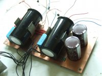
I have built two of the original B1 pre using the original Axion Caps that Pass uses and then a second one with Obligato Premium caps. The Obligatio in my system sounded better with more resolution and smoother. The latest version of pre is capaciterless. The powers supply needs to be redesigned. The design is utterly simple and direct. The sound travels through 2 resistors (Vishay), pot (Blue ALPS) and transistor. A true testament to transparency and this reveals the sound of no caps in the signal path. I once heard that no cap is the best cap.The sound compared to before is alive, better dynamics with bass that goes down to the basement and a coherency that was untouched before. The mid-bass has power that I never thought the 51/4 inch woofers on the satellites could deliver. God I sound like a reviewer!😉 The design is not without risk as it is DC coupled and if you don't know what you are doing you could fry speakers. Not possible in my case.The power supply is a dual bridge with 64000mf (soon to be 88000mF) with CLC topology to filter out high frq garbage. I also used a shunt cap (220 pico) on the input of the pot to get rid of RFI. I know I could go shunt with the regulator but this is so much fun and it rocks! Will try not to break the house today he he! Picture included. Not boxed as of yet. Cheers🙂
I have built two of the original B1 pre using the original Axion Caps that Pass uses and then a second one with Obligato Premium caps. The Obligatio in my system sounded better with more resolution and smoother. The latest version of pre is capaciterless. The powers supply needs to be redesigned. The design is utterly simple and direct. The sound travels through 2 resistors (Vishay), pot (Blue ALPS) and transistor. A true testament to transparency and this reveals the sound of no caps in the signal path. I once heard that no cap is the best cap.The sound compared to before is alive, better dynamics with bass that goes down to the basement and a coherency that was untouched before. The mid-bass has power that I never thought the 51/4 inch woofers on the satellites could deliver. God I sound like a reviewer!😉 The design is not without risk as it is DC coupled and if you don't know what you are doing you could fry speakers. Not possible in my case.The power supply is a dual bridge with 64000mf (soon to be 88000mF) with CLC topology to filter out high frq garbage. I also used a shunt cap (220 pico) on the input of the pot to get rid of RFI. I know I could go shunt with the regulator but this is so much fun and it rocks! Will try not to break the house today he he! Picture included. Not boxed as of yet. Cheers🙂
Attachments

I have B1 ready, and got Lighter note from Uriah recently. I have transformer for Note. Should I buy separate transformer for B1 or I can buy transformer for 2 boards. If yes- which would it be.
BTW Salas low voltage regulator is coming soon- it makes easier to adjust voltage ?
BTW Salas low voltage regulator is coming soon- it makes easier to adjust voltage ?
I have built two of the original B1 pre using the original Axion Caps that Pass uses and then a second one with Obligato Premium caps. The Obligatio in my system sounded better with more resolution and smoother. The latest version of pre is capaciterless. The powers supply needs to be redesigned. The design is utterly simple and direct. The sound travels through 2 resistors (Vishay), pot (Blue ALPS) and transistor. A true testament to transparency and this reveals the sound of no caps in the signal path. I once heard that no cap is the best cap.The sound compared to before is alive, better dynamics with bass that goes down to the basement and a coherency that was untouched before. The mid-bass has power that I never thought the 51/4 inch woofers on the satellites could deliver. God I sound like a reviewer!😉 The design is not without risk as it is DC coupled and if you don't know what you are doing you could fry speakers. Not possible in my case.The power supply is a dual bridge with 64000mf (soon to be 88000mF) with CLC topology to filter out high frq garbage. I also used a shunt cap (220 pico) on the input of the pot to get rid of RFI. I know I could go shunt with the regulator but this is so much fun and it rocks! Will try not to break the house today he he! Picture included. Not boxed as of yet. Cheers🙂
I used the Obbligatos too - brilliant.
With a little imagination they do fit on the original PCB.
The Salas Shunt reg on its own as a PSU is a nice addition too.
Attachments
Gents,
how to make sure b1 is assembled properly before connecting it to the power amp and speakers ?
first timer, not so confident plugging in...
how to make sure b1 is assembled properly before connecting it to the power amp and speakers ?
first timer, not so confident plugging in...
I'm not engineer but i've built several projects and i always follow my own rules and common sense:
- always check twice solder joints and measure continuity searching shorts or bad connections
- check transistor orientation, be sure you don't connect it backwards
- before powering up check PSU voltages, if they arecorrect it's time to cross your fingers 😉
IMPORTANT! forgot to mention:
don't plug it to poweramp at first, it's better to apply power and look for smoke, etc....if everything seems fine connect a source (better a TONE GENERATOR) to preamp input and check output with a DMM). If everything seems fine then connect it to poweramp with volume all way down, switch on, press play on source and turn it up!
I'm sure you'll find better and more technical answers from nice people here!
Thank you
I am using 2 9v batteries for now (basically I bought cheap pcb kit from ebay to practice on, and it was apparently very good decision, as I have some doubts about quality of assembly, and my ldr kit, plus salas psu are waiting for b1 being done).
As I know I can measure some components for specific voltage values and to compare them to given optimal ones- this is I am looking for. If anybody can assist- will much appreciate it..

Are you saying that it's not working?
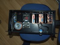
The above photo shows no selector switch or jumper, you might have an open circuit.
The above photo shows no selector switch or jumper, you might have an open circuit.
It is working- on a full volume with no response to potentiometer.
If it is the input selection problem how to place jumper on it then ?
BTW Thank you for response
If it is the input selection problem how to place jumper on it then ?
BTW Thank you for response
?????
That's odd. Something is wired incorrectly.
May we see a well-lit, in-focus photo of your B1 as it is right now? That would be a tremendous help. 🙂
That's odd. Something is wired incorrectly.
May we see a well-lit, in-focus photo of your B1 as it is right now? That would be a tremendous help. 🙂
Cannot upload pics "because security token is missing".
Dropbox:
first
second
full size uncompressed third
I got very bad quality solder, and then I made a mistake with capacitors- had trouble desoldering.
Then I had light diode polarity wrong- and again had desoldering nightmare- for now in place of diode I put a wire jumper.
rest of the things supposed to be ok, not sure about Jfet though...
Thank you! That helps. Your photos are very good quality.
A photo of the bottom of the board would also be nice, to see if you have any bad solder joints.
The problem is that your photos don't show how you are connecting your inputs and outputs. That's where the problem might be.
Without the switch in place I haven't a clue how you are getting a signal to the outputs. ?? Since you say you have full output it makes me think that you are somehow connecting the source directly to the output somehow.
- Status
- Not open for further replies.
- Home
- Amplifiers
- Pass Labs
- B1 builders thread