Manufacturer does not matter.
What are they made of?
Does that suit the duty?
Do they meet specification?
What are they made of?
Does that suit the duty?
Do they meet specification?
often the same thing, when you look for caps at your supplier
and look for the flat square ones, much better than round wound, and size matters 😛
and look for the flat square ones, much better than round wound, and size matters 😛
In my opinion, it is better to use Wima (or other brand) polypropylene (MKP) caps instead this average cheap russian polyester (mylar) in signal path, but they are very robust in common apps.
Could you elaborate your opinion?
There seems to be a general consensus that polypropylene is better sounding
(more neutral) than polyester.
😎
(more neutral) than polyester.
😎
Could you elaborate your opinion?
Mr. Pass said fine, yes - more natural. And if you want extra "sound clearance", use silver mica russian ССГ caps, but they are 0,1 uF maximum. The material does matter.
Just when I thought I all my parts selected I get thrown a curve... Lol...
Now I'm looking at these and thier 1uf versions. Also the MKP10's.
MKP4F051007F00JYSD WIMA | Mouser
Now I'm looking at these and thier 1uf versions. Also the MKP10's.
MKP4F051007F00JYSD WIMA | Mouser
Last edited:
hello everyone.
i am building a preamplifier , i need your help..
which capacitors are best for signal path/coupling? and for power supply?
can i use panasonic M series cap's for signal path or it is better to use mkp cap's?
thank you.
i am building a preamplifier , i need your help..
which capacitors are best for signal path/coupling? and for power supply?
can i use panasonic M series cap's for signal path or it is better to use mkp cap's?
thank you.
Polypropylene seems to be near best for signal coupling.
The caps impedance must be low enough at the lowest frequencies you are coupling to be in effect inaudible.
Electrolytic seems to be good enough for PSU.
The caps impedance must be low enough at the lowest frequencies you are coupling to be in effect inaudible.
Electrolytic seems to be good enough for PSU.
Mouser says
Sorry...corrected link below.
DCP4I051006GD2KYSD WIMA | Mouser
I am leaning twords the MKP10 though but can't find the 1uf varient of the MKP10 with the proper lead spacing for the B1 R0 pcb I have.
Due to the limited space on the B1 PCB for bigger sized caps, has anyone gone ahead and mounted the caps on a separate "daughter" board?? Any comments on this idea?
I am building the B1 Preamp, and as an absolute beginner, I'm having a hard time telling how to orient the 4 JFETs on the PCB. The shape in white outline on the PCB at Q 100,101,200,201 approximates that of the transistor itself. Is this a key to the orientation? Thanks...I'm really enjoying this project so far.
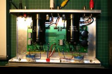
Found this and will be using it to power my B1. Should be interesting.
Put it on the meter and it registered a solid 24.1VDC which can be adjusted +/- 10% I believe.
Invalid Request
ECM40US24 - XP POWER ECM40US24 - AC-DC CONV, OPEN FRAME, 1 O/P, 40W, 1.7A, 24V | Newark element14 Canada


Put it on the meter and it registered a solid 24.1VDC which can be adjusted +/- 10% I believe.
Invalid Request
ECM40US24 - XP POWER ECM40US24 - AC-DC CONV, OPEN FRAME, 1 O/P, 40W, 1.7A, 24V | Newark element14 Canada
B1 help needed please.
I have just completed my B1 build and fired it up to find that I have no attenuation control. It's outputting the full volume regardless of attenuator setting. Both channels have the same problem. I have checked the connections to the Valab mono SMD attenuators installed and they appear to be as Valab's photos. Before I try other attenuators I have on hand, are there any suggestions please?
I have just completed my B1 build and fired it up to find that I have no attenuation control. It's outputting the full volume regardless of attenuator setting. Both channels have the same problem. I have checked the connections to the Valab mono SMD attenuators installed and they appear to be as Valab's photos. Before I try other attenuators I have on hand, are there any suggestions please?
There are normally four wires to an attenuator.
The Input signal Flow and Return.
The Output signal Flow and Return.
The input pair are twisted to help reject interference.
The output pair are twisted to help reject interference.
Where a PCB has commoned the input return and the output return, then you have to choose:
twist all three wires together to create a twisted triplet and run that from PCB to attenuator, trying to minimise LOOP AREAS at the terminations.
or
create a second common near it's signal. Then run a pair from the original common and signal to attenuator AND run a pair from the new common and it's signal to the attenuator.
If the Signal has a common plane then scraping a patch of trace next to the signal pad creates the "new common" and keeps LOOP AREA small.
- Home
- Amplifiers
- Pass Labs
- B1 Buffer Preamp