Hi,
We are getting somewhere!
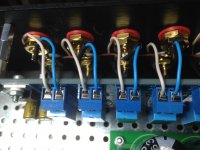
All power related wires are under the baseplate, witch is grounded....
Still waiting for the extender rods and the new attenuator.... The one in the picture is unfortunately broken so I went for a nice Khozmo stepped one from HiFi Collective..... 😎 It should arrive this weekend!
Any tips?
general rule - wire pairs need to go - twisted- through same hole , when going through hole ;
say gnd and +PSU - both wires twisted , through one hole
lazy to explain why
not so critical with DC , but critical with AC ....... it's best to keep it clean and principal for both cases
There have been some monster overkills on the Salas regulator, but to be perfectly honest the design is very good and works with outstanding results as Salas designed it.
Sjoe,
what are the blue and white going from backplate to the blue boxes?
Signal Flow and Return?
These should be, at worst, close coupled pairs.
Far better is twisted pairs.
what are the blue and white going from backplate to the blue boxes?
Signal Flow and Return?
These should be, at worst, close coupled pairs.
Far better is twisted pairs.
The PSU requirements of the B1 are not that critical. Nelson himself used a plain Wallmart wall brick.
I beg to differ. After hearing a stock B1 with a wallwort and a full Salas DcB1 both with stock components, The power supply is critical to the sound of the B1.
I'm beginning to think that the simpler the circuit, the more transparent it is to everything upstream, be it the music source, but also the power source.
Blue and white
Andrew, those are both positive..... Left/right, not pos/grnd
Sjoe,
what are the blue and white going from backplate to the blue boxes?
Signal Flow and Return?
These should be, at worst, close coupled pairs.
Far better is twisted pairs.
Andrew, those are both positive..... Left/right, not pos/grnd
Congrats, absolutely correct being forum a Latin wordI read on different fora that the power source is critical.... Hence this one 🙂
Those are the Hot or Flow part of the SIGNAL.
Where is the Cold or Return part of the SIGNAL?
The Flow and Return must be close coupled all along the route from the Source to the Receiver.
Where is the Cold or Return part of the SIGNAL?
The Flow and Return must be close coupled all along the route from the Source to the Receiver.
Close wires
Hi Andrew,
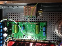
That's the only thing I don't understand about the switch board... it does not have an input ground, only output ground...... So now I connected all the grounds together in line.... This seems strange to me???!!!
Those are the Hot or Flow part of the SIGNAL.
Where is the Cold or Return part of the SIGNAL?
The Flow and Return must be close coupled all along the route from the Source to the Receiver.
Hi Andrew,
That's the only thing I don't understand about the switch board... it does not have an input ground, only output ground...... So now I connected all the grounds together in line.... This seems strange to me???!!!
Attachments
The "output" ground should be the Signal Ground.
It seems the layout of the switching PCB has not been optimised for minimising loop area.
As long as you keep the signal grounds of the input sockets and the ground trace on the PCB close to the "hot" wires and traces you will be keeping loop areas small.
Had you fitted the PCB some distance away and run separate socket ground and signal ground via different routes to a remote Main Audio Ground, you could have had an enormous loop area. By keeping the "inputs" compact you have avoided this bigger problem.
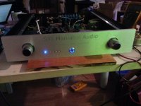
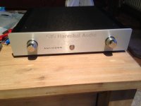
Finished B1
And we are done!
Started listening to it and still am! The detail and headroom is incredible😀
No hum, no nothing😛 just beautifull music 😎
Thanks to all of you who helped me along the way! Ofcourse a big thanks to Mr. Nelson🙂
Merry Christmas to all of you and a very happy new year!

And we are done!
Started listening to it and still am! The detail and headroom is incredible😀
No hum, no nothing😛 just beautifull music 😎
Thanks to all of you who helped me along the way! Ofcourse a big thanks to Mr. Nelson🙂
Merry Christmas to all of you and a very happy new year!
Attachments

Is it possible to run B1 at +30vdc ? already do it with 3 alcaline 9V batteries (27vdc) with great sound; I ask because I get a spare 30vdc regulator . Seem to sound better at 24vdc+, ?
Others try it at around 30vdc .
Others try it at around 30vdc .
Thx 6L6, the regulator is Belleson 2amp., what is your suggestion for capacitor after regulator ?
I hear that changing the 1K resistors to 330 Ohm or 430 Ohm improves the low frequency of this preamp... gets warmer.... ?
Any thoughts on that?
Any thoughts on that?
you can change output resistor (1K) to anything between 0 and 100R
it will be better
Pa put 1K there to increase idiotproof level
it will be better
Pa put 1K there to increase idiotproof level
Resistors
Input resistors will not make any change???? 🙂
you can change output resistor (1K) to anything between 0 and 100R
it will be better
Pa put 1K there to increase idiotproof level
Input resistors will not make any change???? 🙂Point taken
Gotcha!
I did change the output resistors to 12 Ohm.... had them around... must say, more balanced sound, more alive midrange and deeper baseline. For now I'm happy 😀
Thanks!
ya know , parts are having specific (nomenclature) numbers with reason

Gotcha!
I did change the output resistors to 12 Ohm.... had them around... must say, more balanced sound, more alive midrange and deeper baseline. For now I'm happy 😀
Thanks!
Did I do this right????
Attenuator is a Khozmo stepped 50K stereo:
On khozmo "out" is connected to B1 board "W"
On Khozmo "in" is connected to B1 board "CW"
On Khozmo "GND" is connected to B1 board "CCW"
I ask this because I expierience some noise when turning the attenuator....
Merry Christmas!
Attenuator is a Khozmo stepped 50K stereo:
On khozmo "out" is connected to B1 board "W"
On Khozmo "in" is connected to B1 board "CW"
On Khozmo "GND" is connected to B1 board "CCW"
I ask this because I expierience some noise when turning the attenuator....
Merry Christmas!
- Home
- Amplifiers
- Pass Labs
- B1 Buffer Preamp