thanh1973 said:Do you have any idea what I might be doing wrong?
Or is this a common problem with simulators?
common problems with simulators .............. less and less brain-time .....
and less gadgets really made

thanh1973 said:Do you have any idea what I might be doing wrong?
Or is this a common problem with simulators?
Jfet model not that efficient maybe.
I have this one. Changing the Beta, Idss changes. Try to see what happens (if it is not the same already).
.model J2sk170 NJF(Beta=59.86m Rs=4.151 Rd=4.151 Betatce=-.5 Lambda=1.923m
+ Vto=-.5024 Vtotc=-2.5m Cgd=20p M=.3805 Pb=.4746 Fc=.5
+ Cgs=25.48p Isr=84.77p Nr=2 Is=8.477p N=1 Xti=3 Alpha=10u Vk=100
+ Kf=111.3E-18 Af=1)
.model J2sk170 NJF(Beta=59.86m Rs=4.151 Rd=4.151 Betatce=-.5 Lambda=1.923m
+ Vto=-.5024 Vtotc=-2.5m Cgd=20p M=.3805 Pb=.4746 Fc=.5
+ Cgs=25.48p Isr=84.77p Nr=2 Is=8.477p N=1 Xti=3 Alpha=10u Vk=100
+ Kf=111.3E-18 Af=1)
I just tried your model, but still the same result (ie mostly 3rd Harmonic with no 2nd Harmonic)
If you have LTspice, I could send you the circuit to have a look at.
I am not quite sure if I have earthed everything correctly.
If you have LTspice, I could send you the circuit to have a look at.
I am not quite sure if I have earthed everything correctly.
Hi tanh, I havent simulated this circuit but I for one think it would display more h3 than second, playing around with values should make h2 dissapear. I dont think the guys that get h2 to be above have the exact same circuit as in the pass paper, and if I remember correctly NP himself said it would be predominantly h3.
Well I hope so.
I am learning heaps at the moment using LTspice - changing values or components looking at the effects, determining dc offset, bias currents, input impedance, and also looking at the distortion profile.
It has also been a source of motivation to try tweeking things where as before, I would be totally relying on ohers experience or guessing.
Anyway, I hope as you say it is predominantly H3, or all confidence I have in simulators will be lost.
Unless I can find the source of this discrepancy.
With a 23-25 V supply and 1 Khz at one volt into 10 Kohm, I routinely
see .0007% with BL parts.
😎
see .0007% with BL parts.
😎
I will see near that when I will get my new EMU 24bit I guess. You must be using AP2? The main question is do you still see more second than third harmonic in your FFT like I do? I used 0dBV input, volume fully clockwise, about 3k card input Z.
I use the AP1 - the later products are too fancy for me, but we have an
AP2 on one of our benches here.
😎
AP2 on one of our benches here.
😎
Hi Nelson
It would be nice if you could let us know if the B1 as per the the original design is predominantly 2nd or 3rd order harmonic distortion.
It would be nice if you could let us know if the B1 as per the the original design is predominantly 2nd or 3rd order harmonic distortion.
Thanks Nelson
OK then hopefully I have made a mistake somewhere.
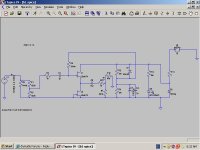
Can someone check the way I have drawn the circuit.
I am a little unsure about the signal ground/return and output ground/return, and the DC power ground/return.
Any help would be most appreciated.
Thanks
OK then hopefully I have made a mistake somewhere.
Can someone check the way I have drawn the circuit.
I am a little unsure about the signal ground/return and output ground/return, and the DC power ground/return.
Any help would be most appreciated.
Thanks
Attachments
thanh1973 said:Thanks Nelson
OK then hopefully I have made a mistake somewhere.
Can someone check the way I have drawn the circuit.
I am a little unsure about the signal ground/return and output ground/return, and the DC power ground/return.
Any help would be most appreciated.
Thanks
You do not have things setup completely for an FFT with LT Spice. Try adding the following directives.
.tran 0 30m 0.1u
.step param C list .100u .10100u
.option plotwinsize=0
Test at 1000Hz.
If you want to learn more about LT Spice. Try the forum for it on groups.yahoo.com. I am unable to help you further. I just copied the above from an example I found there. It works for me.
Jim
Just simmed tanh s circuit and indeed it shows that h3 dominates.
Tanh do the sim now at 20Khz and I think youll be even more puzzeled
Tanh do the sim now at 20Khz and I think youll be even more puzzeled
Whenever spice doesn't match measurement, we look for flaws
in the models first. This would not be the first time that Spice JFET
models have come up a little short.
😎
in the models first. This would not be the first time that Spice JFET
models have come up a little short.
😎
Mr. Pass
I read a post by you that mentioned using the AP1 and some other attenuator after the source and before the amp with a buffer or pre inbetween. I cant for the life of me find it now. You talked about maybe having just a few different resistances to choose from before the buffer/pre and then after it to have, I think, the AP1.
Is this to help 'rectify' any source output/amp input impedance issues or what is the reason?
I think this was with a BOSOZ.
Thanks
Uriah
udailey said:Mr. Pass
I read a post by you that mentioned using the AP1 and some other attenuator after the source and before the amp with a buffer or pre inbetween. I cant for the life of me find it now. You talked about maybe having just a few different resistances to choose from before the buffer/pre and then after it to have, I think, the AP1.
Is this to help 'rectify' any source output/amp input impedance issues or what is the reason?
I think this was with a BOSOZ.
Thanks
Uriah
AP1 is measuring gadget , almost capable of computing 42 .
we don't ( we - spoiled kids ) even need to know exactly what's that beast ..........
anyway - I can just imagine using it as attenuator
- Home
- Amplifiers
- Pass Labs
- B1 Buffer Preamp