how does the 3.7mm drill bit fit with a 1.5mm ferrule?
The 1.5mm probably refers to the inside diameter or the thickness of the cables to be joined. 3.7mm is therefore the outer diameter, but it can differ slightly from supplier to supplier I found.
I have ferrules, but they are sized by the cross sectional area of the stranded copper that fits into the hole, i.e. 0.5mm^2, 0.75mm^2, 1mm^2, 1.5mm^2, 2.5mm^2
The 1.5mm^2 ferrule measures approximately 1.64mm bore/i.d. and 2.09mm o.d. (giving a wall thickness of ~9thou/mil).
Where is your 3.7mm drill going to fit with that?
The 1.5mm^2 ferrule measures approximately 1.64mm bore/i.d. and 2.09mm o.d. (giving a wall thickness of ~9thou/mil).
Where is your 3.7mm drill going to fit with that?
Last edited:
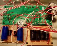
Finished my low cost B1 the weekend. I used matched BF862’s as straight replacements for the 2SK170’s. The PCB is my own implementation of point-to-point, by positioning the components on Perspex. I am not clever/crafty enough to do dead-bug style. Largely Vishay components used – MKP 1839 and MKP 1848 caps with RN55 resistors. Powered by a 19V laptop brick. Apart from using BF862’s the only other mod was changing the output resistors (R104, R204) from 1K to 100R.
Hi diyRookie,
please, 2 questions:
1. why have you changed output resistors?
2. I can not see it from photo, did you use any gate ressistor for BF862?
Thank you,
t.
Hi diyRookie,
please, 2 questions:
1. why have you changed output resistors?
2. I can not see it from photo, did you use any gate ressistor for BF862?
Thank you,
t.
Great build, Some more details on BF862's will be helpful, i only have SMD version, not sure if they come in the normal transistor package...and gate resistor rating...Idss values....I desperately am looking for 2SK replacements.....
Sent from my iPhone using Tapatalk Pro
BF862's are pretty much the "go-to" N-JFET for audio nowadays for me. They are SMT but not too hard to solder directly to thru hole pads. It is interchangeable Source and Drain so makes it easy. You can buy a small SMT pad adapter to test idss or make your own with a simple etch. Ranges are very similar to 2SK170BL and they sound real nice. I have a bunch of headphone amps that use them. You can listen to them here.
http://www.diyaudio.com/forums/headphone-systems/303345-blind-virtual-audition-several-headamps.html
http://www.diyaudio.com/forums/headphone-systems/303345-blind-virtual-audition-several-headamps.html
Well thank you for the info 🙂.
Not to hijack the topic, it would be important to find out can BF862 be used in B1 (without sound degradation), and what are (if any) adjustments/limitations. Since 2Sk170 is widely used in audio projects, and with limited availability (only getting worse), having cheap alternative is important. It's not that buying couple os 2sk's is expencive or difficult, but buying couple of dozens needed for matching - could be.
Back to diyRookie, please, one (two?) question(s) more:
1. i did not found voltage supplied to your B1?
2. Can you please observe, if not measure, thermal status (temperature) of BF862? It would be safe (in voltage sense) to touch it, but I do not know is temperature high enough so it can burn you (I guess not, but better be safe than sorry). If you can do it, please makse sure B1 was on for some reasonable time..
Thank you
The BF862 can take 300mW and up to 20v. I find that SMT parts dissipate heat better as they are in contact with the board. The legs themselves actually conduct quite a bit away onto the PCB. I have exchanged BF862 and 2SK170's on several projects with great results. Basically interchangeable for all intents and purposes. And you can buy a reel of 100 for not much money.
Here are a bunch matched using jig that represents tbe actual circuit it will be used in. Or in-situ matching for Idss.
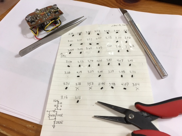
Here are a bunch matched using jig that represents tbe actual circuit it will be used in. Or in-situ matching for Idss.
Last edited:
Answer I was hoping for 🙂
Gate resistor? Yes/no, if yes - value (recommanded/minimum/calculculated)?
So SMT parts (to be more specific bf862) is better to be soldered to adapter pcb and than on main board, rather than connection via legs to main pcb? (Heatvise)
No need for extra cooling/pads/heatsink? Again, talking about b1, possible other circuits (aca, dcb1...).
As for matching, normally I would use several times published simple circuit, both by Mr Pass and Mr. Borberly, but very good idea to use actuall circuit!
Thank you
Hi diyRookie,
please, 2 questions:
1. why have you changed output resistors?
2. I can not see it from photo, did you use any gate ressistor for BF862?
Thank you,
t.
Hi tborzic,
Mr. X can better answer your technical questions.
But to answer some:
1. I changed the output resistors based on a post I have seen. Someone asked:
"I hear that changing the 1K resistors to 330 Ohm or 430 Ohm improves the low frequency of this preamp... gets warmer.... ?
Any thoughts on that?"
ZenMod answered: "you can change output resistor (1K) to anything between 0 and 100R - it will be better"
2. I did not use any gate resistors. I do recall that someone (probably AndrewT) suggested to use some (100R I think), or even ferrite beads. So, I don't know if my B1 has a problem with oscillations. It does sound good. How/what will I hear if there are oscillations?
Sorry, I have not tried to touch the BF862's for temperature - will maybe try that sometime. My BF862's have relatively long (20mm) thin solid wires soldered to them (they look like mosquitoes on stilts), so I hope that would be enough to dissipate the heat. Mr. Pass once said that these jfets are more robust than we think. I can just imagine how hot they get while soldering them - yet they still function after that.
just finished B1
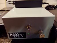
Finally got a break and completed my DIY Pass B1 as my 4th diy electronics project.
I used the smallest Hammond enclosure that would accept the power caps height ,which made it a little bigger than I would have preferred. The long chassis sides seemed a little thin for the input and output jacks so I used the shorter depth side for mounting . The downside is I had to make the wiring a little longer to facilitate the top getting attached.
On my last project , the Folsom chip amp, I used stranded hookup wire, but this time I used solid copper insulated bell wire from Home Depot and soldering was better for me. Reading Nelson Pass's blog page on soldering helped me too.
The input caps were a bit large for the board so I mounted them on separate boards to anchor them. The switch selects either channel one or channel 2 input, but no off position so I may have not ordered the correct switch from digi-key . The unit is in the basement exercise area so it is always shut down at the power supply when not in use anyway . I included a CD to show scale .
DACT knob is salvaged from a DOA tank like Toshiba cassette deck someone gave me.
So far I'm very pleased with the "sound" performance of the B1 in the setup and already decided it would be a good thing to build the next Mesmerize version for my main listening room.
Attachments
The chassis mount metal power jack plug from Parts Express worked well but you have to drill the hole very close including de-burring as the outside lip of the plug is barely larger than the barrel. Hardly any wiggle room
I am connecting two power amplifiers with RCA splitters from my B1. Would that cause any damage to the B1?
a question , is operation of the B1 is always volume up all the way or is my power amp / integrated amp up all the way and system volume controlled by the B1 ?
thanks
thanks
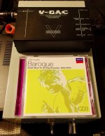
Source is either a TASCAM CDPlayer-200 or Mac Mini > to Schitt Uber Bifrost DAC feeding either a Jolida 202 tube amp or a Nuera Class A SET amp .
In the basement it is a Sony CD/DVP-S360 player to a Musical Fidelity V-DAC ver. I feeding a Audio Source Amp 100 ( upgraded with better components by Tyger )
thank you
In the basement it is a Sony CD/DVP-S360 player to a Musical Fidelity V-DAC ver. I feeding a Audio Source Amp 100 ( upgraded with better components by Tyger )
thank you
As all your amps have attenuators, there's no right or wrong answer.
Try it both ways - B1 wide open and volume on the amps, or amps set to OMG loud and volume on B1.
It's very likely that one way will sound better to you.
Try it both ways - B1 wide open and volume on the amps, or amps set to OMG loud and volume on B1.
It's very likely that one way will sound better to you.
It has been recommedned to duplicate the 1k output resistors for each output channel.
Thank you AndrewT. Still unclear if it can cause any damage if you don't connect the resistors?
- Home
- Amplifiers
- Pass Labs
- B1 Buffer Preamp