transformer sources
I checked out Lundahl and Sowter as well as Jensen. Jensen had the most coherent rap, spec sheets, and information, as well as access to Bill Whitlock who responded with detailed information and advice.
Gary Galo in (Audio Xpress 2007 "Lundahl and Jensen Meet the Monarchy M24"), seemed to prefer the Jensen transformers for his application, but this was not the JT-11P-1 I am using.
Ummm... all is well!
I could call myself several things... oh the shame of being the ONLY DIYer not able to get a B-1 working. 😱 Like I tell my students... "thinking is allowed," RTFM etc. etc. I found the err.. mine of course. Something about the minor detail of making sure the input signal actually gets to the circuit. I thought I was being clever with an off-board volume control and input selector. Apparently not clever enough.
Thanks for the quick replies and support. The drain voltages told me things should be working properly and so I looked elsewhere and found the fault.
It is working fabulously and I am listening at this very moment. The pre that it replaced is now relegated to the garage system. I still need to add a better power supply. Even as it is, I do really, really like the B-1!
Thank you Mr. Pass!
Cheers,
Ryan
Combining benefits of DCB1 with B1
After reverting back to the B1 with the Dual Regulated Salas supply I thought what a waste of a dual regulated supply.
I'm just throwing together some spare components to see if I can produce a single rail Shunt Reg Supply so that I can use the +/-10 V Dual Reg for better things.
You might wonder about my choice of components, but they are what I have lying around.
I'm using 2 x IRF130 which would normally produce the -ve rail but this makes no difference to the B1.
Can anyone spot any obvious design flaws. I'm aiming for about 22-24V out but its not that critical.
Attachments
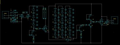
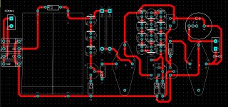
The PCB design checks with the schematic so any errors are not with the transcribing of one to the other.
I know that C3 is shown the wrong way round, that's the cap across the long LED string. It's unimportant as its a polyprop anyway.
22V only calls for 11 x GREEN LEDs. I've only put 12 in the string to allow for adjustment.
I know that C3 is shown the wrong way round, that's the cap across the long LED string. It's unimportant as its a polyprop anyway.
22V only calls for 11 x GREEN LEDs. I've only put 12 in the string to allow for adjustment.
Last edited:
DIY B1 with Salas Shunt Reg
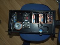
Just for completeness, here is my final product.
A DIY B1 with a Salas +/-9.6V = 19.2V Shunt Reg biassed at about 125mA.
At 125mA the enomous heatsinks are overkill but I had them anyway and they keep everything nice and cool.
Please refer to the http://www.diyaudio.com/forums/pass-labs/145201-building-symmetrical-psu-b1-buffer-254.html
thread for details about the Shunt Reg.
Attachments
Last edited:
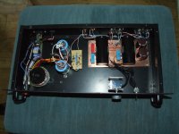
Personally I couldn't hear any difference between the Salas Dual Reg and the LM317 Reg running at 22V.
Do you reckon there might be any benefit in building the single Shunt Reg supply over the Dual Reg ?
The photo is the previous incarnation with the LM317.
Do you reckon there might be any benefit in building the single Shunt Reg supply over the Dual Reg ?
The photo is the previous incarnation with the LM317.
Attachments
Personally I couldn't hear any difference between the Salas Dual Reg and the LM317 Reg running at 22V.
Do you reckon there might be any benefit in building the single Shunt Reg supply over the Dual Reg ?
The photo is the previous incarnation with the LM317.
Assuming you used the recommended huge filter capacitors on the B1 board, I'd say it shouldn't make a bit of difference which regulator you used. Heck, use a wall wart and make it even more simple. Mr. Pass did that, didn't he?
A laptop-style SMPS power supply, but still a wall wart.
KatieandDad - If it sounds good, is fully functional and hummm free probably the best thing you could do is put the cover on it and listen. Start a new project. Power amps are rather fun, as are speakers. 🙂 🙂 🙂
KatieandDad - If it sounds good, is fully functional and hummm free probably the best thing you could do is put the cover on it and listen. Start a new project. Power amps are rather fun, as are speakers. 🙂 🙂 🙂
Last edited:
Nelson did it his way for a reason. I'm tempted to agree with the original design.
A cheap Wallmart might be pushing things but a decent CRC supply certainly sounds, to me, just as good as a full blown Shunt Reg.
I started with a 15VA standard bridge with 4700uF. This was betterred by a 30VA with an LM317 regulator. Above that I couldn't hear any improvement.
And YES, my B1 does have the 2 x 15000uF Panasonics, all PSU caps are bypassed with 100nF Polydrops and even the Obbligato 10uFs are bypassed with 1n5F Polystyrenes.
I'm more than happy with the result.
Last edited:
I checked out Lundahl and Sowter as well as Jensen. Jensen had the most coherent rap, spec sheets, and information, as well as access to Bill Whitlock who responded with detailed information and advice.
Gary Galo in (Audio Xpress 2007 "Lundahl and Jensen Meet the Monarchy M24"), seemed to prefer the Jensen transformers for his application, but this was not the JT-11P-1 I am using.
I like your layout and the copper panels. Is the orientation of the input transformers critical? With the standard mu metal can, is it ok to place them a few inches from each other? How long are your leads from the transformer output to your coarse attenuator?
I like your layout and the copper panels. Is the orientation of the input transformers critical? With the standard mu metal can, is it ok to place them a few inches from each other? How long are your leads from the transformer output to your coarse attenuator?
%%%%%%%%
The single ended to differential transformers are at most 4 inches away from the attenuators, and 10 inches away from each other. I used twisted pair, physically separate for left and right. I keep SE and diff leads separate, to reduce capacitance between the separate grounds. Pay attention to the Jensen wiring and shield specs.
As per a suggestion by Nelson Pass, I separated the various grounds, ie left single ended (SE), right SE, left diff, right diff, with back to back diodes , so that all the grounds AC wise can float by 0.7 volts. I think I will install some 3V TVS (transient voltage suppressor, surface mount gizmos) instead.
I think a few inches (more than one inch) of air is sufficient to give excellent channel separation, but I did not do any measurements to prove this, although this is what we did for executing the design. It sounds really good, though.
I wish we had the $$ to check out different transformers and see if there are useful differences between Sowter, Lundahl, Jensen, etc.
Most of our critical listening is done in fully differential mode though.
Thanks for the info!
Your grounding scheme is very interesting and I want to learn more about that for a future balanced project, if I can get to it. I am considering having a bal input option via transformer for my Hypnotize build, but using the secondary unbalanced, to keep the standard setup beyond the front end. I think the voltage difference between +4 and -10 dBu will easily be handled by the Pass pre without padding. Though I'd like to hear your opinion on that.
I think you really thought it through superbly and thanks for posting it here.
I have decided to go with Cinemag transformers and I'll let you know how it works out. The secondary wants a 10kOhm load, so, in my existing pre, not the Hypno yet, I will change out my 20k pot to a 10 kOhm.
Fun stuff.
%%%%%%%%
The single ended to differential transformers are at most 4 inches away from the attenuators, and 10 inches away from each other. I used twisted pair, physically separate for left and right. I keep SE and diff leads separate, to reduce capacitance between the separate grounds. Pay attention to the Jensen wiring and shield specs.
As per a suggestion by Nelson Pass, I separated the various grounds, ie left single ended (SE), right SE, left diff, right diff, with back to back diodes , so that all the grounds AC wise can float by 0.7 volts. I think I will install some 3V TVS (transient voltage suppressor, surface mount gizmos) instead.
I think a few inches (more than one inch) of air is sufficient to give excellent channel separation, but I did not do any measurements to prove this, although this is what we did for executing the design. It sounds really good, though.
I wish we had the $$ to check out different transformers and see if there are useful differences between Sowter, Lundahl, Jensen, etc.
Most of our critical listening is done in fully differential mode though.
B1Buffer transformer loading, ground schemes
If you load the transformer with a 20 kOhm resistor, then it plus your existing attenuator in parallel will yield 10kOhms.
+4dBu is sine wave peak amplitude of 1.737 V, or peak to peak twice this. Just make sure you have sufficient DCPS headroom to accomodate lots more than that. The JFETs are rated at max V_DS = -30 to -40 volts, but they are matched generally at -10 volts.
I am going to add 1 M-Ohm resistors in parallel to the grounding "isolation" diodes, set the DC ground levels to zero but allow AC float, but it is already extremely quiet, so I dont know if this will be an improvement or not.
Thanks for the info!
Your grounding scheme is very interesting and I want to learn more about that for a future balanced project, if I can get to it. I am considering having a bal input option via transformer for my Hypnotize build, but using the secondary unbalanced, to keep the standard setup beyond the front end. I think the voltage difference between +4 and -10 dBu will easily be handled by the Pass pre without padding. Though I'd like to hear your opinion on that.
I think you really thought it through superbly and thanks for posting it here.
I have decided to go with Cinemag transformers and I'll let you know how it works out. The secondary wants a 10kOhm load, so, in my existing pre, not the Hypno yet, I will change out my 20k pot to a 10 kOhm.
Fun stuff.
If you load the transformer with a 20 kOhm resistor, then it plus your existing attenuator in parallel will yield 10kOhms.
+4dBu is sine wave peak amplitude of 1.737 V, or peak to peak twice this. Just make sure you have sufficient DCPS headroom to accomodate lots more than that. The JFETs are rated at max V_DS = -30 to -40 volts, but they are matched generally at -10 volts.
I am going to add 1 M-Ohm resistors in parallel to the grounding "isolation" diodes, set the DC ground levels to zero but allow AC float, but it is already extremely quiet, so I dont know if this will be an improvement or not.
HI, i want to try this nice buffer and ai have onlu 2sk170GR Idss around 5-6ma. They are ok for B1 buffer? Should i adjust some values durind build ? Thanks!
My understand about matching the jfets is that you need to match the Idss as close as you can for the constant current source and the buffer. (I.E., the 2 fets in each channel) The actual value is not as important as the closeness of the match.
matching JFET transistors and choice of I_DSS grade
I matched my jfets both for I_DSS at V_GS=0volts (to < 1%) , and for pinch off voltage, both to 2%. The gain figure of merit follows from the pinch off voltage, and
The voltage noise in JFETs will be lowest when the devices are operated
at VGS = 0 V (ID = IDSS), where transconductance is at its highest value.
The current noise is optimum (lowest) in in depletion-mode JFETs should
also occur at VGS = 0 V (ID = IDSS).
This means that the current source for a cascode circuit where there is a current bias JFET for another JFET gain transistor is operating in a low noise regime (ie V_GS=0)
The current noise figure is slightly better with larger transconductance which is larger drain current, ie I_DSS, but not much. Therefore it does not look like much of a noise penalty hit for lower current grade JFETs (grade GR=> I_DSS=5mA, BL=>I_DSS=10mA).
A little more detail can be found on the web at - intrator.dyndns.org/B1Buffer.html
and with this application note from Siliconix
My understand about matching the jfets is that you need to match the Idss as close as you can for the constant current source and the buffer. (I.E., the 2 fets in each channel) The actual value is not as important as the closeness of the match.
I matched my jfets both for I_DSS at V_GS=0volts (to < 1%) , and for pinch off voltage, both to 2%. The gain figure of merit follows from the pinch off voltage, and
The voltage noise in JFETs will be lowest when the devices are operated
at VGS = 0 V (ID = IDSS), where transconductance is at its highest value.
The current noise is optimum (lowest) in in depletion-mode JFETs should
also occur at VGS = 0 V (ID = IDSS).
This means that the current source for a cascode circuit where there is a current bias JFET for another JFET gain transistor is operating in a low noise regime (ie V_GS=0)
The current noise figure is slightly better with larger transconductance which is larger drain current, ie I_DSS, but not much. Therefore it does not look like much of a noise penalty hit for lower current grade JFETs (grade GR=> I_DSS=5mA, BL=>I_DSS=10mA).
A little more detail can be found on the web at - intrator.dyndns.org/B1Buffer.html
and with this application note from Siliconix
Attachments
B1 unbalanced to balanced Son of Zen
Hi all,
This is my first post and I'm not an electrical engineer so please excuse me if I ask something ridiculous.
I recently decided to build myself a B1 buffer and have collected all the parts for it. Last weekend however, I was gifted a pair of Son of Zen (SOZ) mono blocks (will post pics soon). The write up for the SOZ at Passdiy suggests that the SOZ was designed to accept a balanced input. The B1 buffer has an unbalanced output. I have not constructed the B1 as yet. My questions are:
1) Is is possible to build the B1 with balanced outputs if so, would it be difficult to achieve this, or is it just a matter of switching to XLR connectors.
2) From a SOZ standpoint, would using an RCA to XLR interconnect be electrically appropriate. Would this affect sound quality adversely.
Thanks,
Nikhil
B1 Buffer differential
I decided to build 2 channels for each channel, to make it differential. Then you would need to PC boards to make 2 differential stereo channels. That required me to match all components to 0.1% or better. ).1% corresponds to 60dB of common mode rejection, and it is likely that 80 dB would be better. In any case, you could do this at home but probably any production line situation for commercial products might have expensive trouble doing this. Typically good common mode rejection is done with feedback circuits which is what I was trying to avoid.
You can find the schematics and pictures at intrator.dynds.org or previous posts on this thread.
regards
Tom Intrator
Hi all,
This is my first post and I'm not an electrical engineer so please excuse me if I ask something ridiculous.
I recently decided to build myself a B1 buffer and have collected all the parts for it. Last weekend however, I was gifted a pair of Son of Zen (SOZ) mono blocks (will post pics soon). The write up for the SOZ at Passdiy suggests that the SOZ was designed to accept a balanced input. The B1 buffer has an unbalanced output. I have not constructed the B1 as yet. My questions are:
1) Is is possible to build the B1 with balanced outputs if so, would it be difficult to achieve this, or is it just a matter of switching to XLR connectors.
2) From a SOZ standpoint, would using an RCA to XLR interconnect be electrically appropriate. Would this affect sound quality adversely.
Thanks,
Nikhil
I decided to build 2 channels for each channel, to make it differential. Then you would need to PC boards to make 2 differential stereo channels. That required me to match all components to 0.1% or better. ).1% corresponds to 60dB of common mode rejection, and it is likely that 80 dB would be better. In any case, you could do this at home but probably any production line situation for commercial products might have expensive trouble doing this. Typically good common mode rejection is done with feedback circuits which is what I was trying to avoid.
You can find the schematics and pictures at intrator.dynds.org or previous posts on this thread.
regards
Tom Intrator
You should look at the balanced Zen linestage - also know as the 'Bride of Son of Zen'
http://www.passdiy.com/pdf/balzenpre.pdf
http://www.passdiy.com/pdf/balzenpre.pdf
- Home
- Amplifiers
- Pass Labs
- B1 Buffer Preamp