Thanks again guys,
My B1 is still up and burning in nicely after almost a week now.
I will post photos at some point over in the builders thread.
Thanks again,
Keith Lockwood
My B1 is still up and burning in nicely after almost a week now.
I will post photos at some point over in the builders thread.
Thanks again,
Keith Lockwood
Dear All,
My first post on this section of the DIY forum.
I did not understand if this buffer stage as any gain. I have a tube 300B amplifier, with the headphone output of my pre the volume is high enough, but if I connect the CD with a passive preamplifier, the level is too low.
If the B1 has a bit of gain could solve my problem, and I like the fact that has no feedback.
Thanks,
Davide
Davide,
The B1 has no gain. You already know that you need gain. I would wait for one of Nelson's upcoming projects that will include some voltage gain as part of it's design. I can't remember off the top of my head if it is designated B2 or B3. One of those will be of interest to you. Seems like I remember it is B3.
I hope someone will chime in an correct me if I am wrong. I seem to remember that B2 is the unit designed for integrating full range drivers like the Lowthers, Fostex, or Feasterex with a larger bass driver and facilitating crossing them over for good integration.
Keith
Davide,
It is possible that your passive preamp is loading your CD player. To test for that, plug in your CD player directly to your amp. That is the maximum volume a B1 will provide.
Otherwise, Keith is correct that something other than the B1 is required.
Doug
It is possible that your passive preamp is loading your CD player. To test for that, plug in your CD player directly to your amp. That is the maximum volume a B1 will provide.
Otherwise, Keith is correct that something other than the B1 is required.
Doug
Member
Joined 2002
Thank you Uriah.
Those came from Papa at the first BA. Many thanks to NP for the old school Threshold knobs.
Where is the picture of the nice sexy silver wire 🙂
I recently wired up a B1 (point to point, mostly components from the article on passdiy) and put it into my system for a quick test. Sounds great to me! Before I stick it into a case I wanted to run some tests - I have a software signal generator and an old oscilliscope at my disposal.
I am just wondering what to use as the load across the output of the B1 when I test? In the article when talking about roll-off a 10k load and a 47k load is mentioned so I am guessing a 10k resistor across the output would be a reasonable load to compare input and output on the oscilloscope?
Any advice is appreciated.
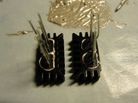
Following our Dual JFET heatsink for diff pair applications :
http://www.diyaudio.com/forums/group-buys/135359-toshiba-dual-jfet-heatsink.html
We made two further variants for our own dual-rail, B1-type buffer for use in a line-level, variable BSC filter. This allows 2x 2SK170 (or any TO92 device like 2SK369, 2SJ74, .....) to be mounted side by side, so that the source of one is next to the drain of the other, as in the schematics. The two versions have the JFETs mirrored relative to the heatsinks, to allow for layout flexibility.
The photo on the right shows the gluing process with Arctic Silver.
Patrick
.
Attachments
Last edited:
Hi,
I like to create this buffer and have some components of former projects ...
Can I use 11uF capacitors or 12 uF to 10 uF replacing the scheme is original? Affect the sound?
Thank you all for this thread and Mr. Pass for his design.
AL
I like to create this buffer and have some components of former projects ...
Can I use 11uF capacitors or 12 uF to 10 uF replacing the scheme is original? Affect the sound?
Thank you all for this thread and Mr. Pass for his design.
AL
Here is a handy calculator
Guitar Pedals: R-C Filter Calculator
Note the cutoff for the high pass filtering in lite of the input impedance for your power amplifier. My bet, the 11 or 12 uf will be fine. Perhaps better if you spare parts are metalized polypropylene.
Guitar Pedals: R-C Filter Calculator
Note the cutoff for the high pass filtering in lite of the input impedance for your power amplifier. My bet, the 11 or 12 uf will be fine. Perhaps better if you spare parts are metalized polypropylene.
Thanks lae2
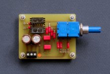
My B1 is finished.
A very clean and clear sound, less noise than the preamp of my MF A308 amp.
Only one thing I would adjust to terminate the prototype.
If I turn on the preamp after amp sounds a blow pop in the speakers, is strong.
How can I reduce this blow to the amplifier to turn on the preamp?
I placed a stepped resistor attenuator 10K
I have other devices that do but at a much lower level.
P.D.: excuse my English, I used a translator.
add a delay on mute and fast off mute.
If you monitor the B1 output voltage during start up and power off, you will find offsets that are hundreds of times higher than the output offset that exists in quiescent conditions.
The mute can be a relay or a transistor.
If you monitor the B1 output voltage during start up and power off, you will find offsets that are hundreds of times higher than the output offset that exists in quiescent conditions.
The mute can be a relay or a transistor.
I put a relay in the output of B1 with a delay of 4 seconds and even then there is the blow when the relay passes the signal to the amp.
I put a relay because there was also a blow to power off that was deleted.
How do I measure the output offset b1?
Is it possible that the blow because of the Relay?
thanks for your help
I put a relay because there was also a blow to power off that was deleted.
How do I measure the output offset b1?
Is it possible that the blow because of the Relay?
thanks for your help
Do you have R1, C1, C2 and C3 in the circuit? Is the polarity correct for C1 and C2? If so, the FETS should be delayed in coming up to bias. I wonder if your "blow" might be a grounding issue. I would expect that a relay on the output would cause a "blow."
Hi,
all components have been correctly loaded.
I think I've located the problem. When I turn on the B1, the current in the signal output (L and R) is greater than two minutes elapsed.
After a few minutes, if you turn off and on quickly ... NO "BLOW"
Is this due to the design of the B1 or have connected something wrong?
The B1 is single ended and must be capacitor coupled at both input and output.
These capacitors need to charge up at start up and to discharge at shut down.
These charging/discharging currents cause enormous offsets during start up and shut down. A time delayed mute is virtually mandatory.
The DCB1 is direct coupled and requires the output to be at signal ground level. This too suffers output offsets during start up and shut down.
The standard DCB1 PCB (Hypnotize) has a timed delayed muting relay to help avoid these offsets getting to the next stage. But the mute must be delay ON and instant OFF, or as close to that ideal as the circuit allows.
I am about to install the PEC volume pots onb my B1, but there's no documentation on the terminals. Does anyone know which is gnd, input, output on the PEC?
Nelson,
I have an off topic question for you. What was the name of the gentleman who was your national sales manager for Threshold during the mid eighties? I was the manager at one of your dealerships and we saw him quite often and remember that he was a pleasant fellow. Seems he moved on to a pro sound company called Myers Sound or something like that?
If this isn't the proper place for a question like this just ignore it.
Keith Lockwood
The center is the wiper, and the other two are positioned
just as you would imagine them.
😎
Gracias
Beginner mistake: I installed D1 in the wrong direction.
I plugged it in (unknowing) and after a short warm up music played at a seeming reasonable volume. The LED worked and I guessed everything was ok. After some extended listening some strange "hum" cam into the circuit and I shut it down. More or less the same thing happened for a few times. Now it seems the hum is there all the time and the LED fades out quickly when powered on.
Anyway, I was wondering if someone could help me explain what is happening. From what I understand, D1 would essentially act like a short circuit allowing current to bypass R2 and pulling the gate up to drain on Q100 and Q200. I measured the voltage across C2 and it was ~18V which fits in with this.
What I don't understand is why it worked at all, and what started to go wrong after some listening? Also when I measured the voltage across C1 it was 0 and what is going on with the LED?
Any help is appreciated.
- Home
- Amplifiers
- Pass Labs
- B1 Buffer Preamp