Proper tightening of the outputs would be something to take note of also, hard to describe really, and may be worth finding a tiny torque wrench even depending on your confidence.
I have much older amplifiers that are still using the original main filter capacitors, I would put my attention towards the driver boards as you have mentioned unless you have unlimited budgets. The smaller capacitors tend to dry out earlier than the large ones.
I worked on a parasound a while back that benefited from replacing the 100uf with some Nichicon kz I think it was, and the yellow polystyrene parts were also improved with some Russian surplus polystyrene.
The input capacitor will be tougher to recommend a replacement as there are so many variables with tastes, other equipment, physical space in which to locate parts, budget, etc.
I recently had used some wima mkp10, since they were the largest that could be used in my case, sound good, are reasonably priced. The electrolytic part that’s there now is probably 100uf, but the film replacement will only need to be more like 4.7uf.
Proper tightening of the outputs would be something to take note of also, hard to describe really, and may be worth finding a tiny torque wrench even depending on your confidence.
I have much older amplifiers that are still using the original main filter capacitors, I would put my attention towards the driver boards as you have mentioned unless you have unlimited budgets. The smaller capacitors tend to dry out earlier than the large ones.
I'm comfortable with not over tightening. But good thing to point out. I would agree that larger ps caps last longer than the smaller board caps ... at least in my experience. The output boards will be the first stage of my work. I can afford it and once parts are in, I can get done in an evening, and it's fun, and somewhat therapeutic. 🙂
Replacing the larger power caps can be done easily, later. But I'll reflow solder traces on the ps board and make sure it's all good. One thought I had is if there is any value of selling the stock caps to someone wanting a cheap replacement for non-working caps? I'm guessing if so, they might be worth $25-50 both? I'm penny pinching here, so pardon me. The other question is if I continue using the old ps caps ... will there be any warning when they are going bad, so I can stop using the amp until I replace them?
I worked on a Parasound a while back that benefited from replacing the 100uf with some Nichicon kz I think it was, and the yellow polystyrene parts were also improved with some Russian surplus polystyrene.
The input capacitor will be tougher to recommend a replacement as there are so many variables with tastes, other equipment, physical space in which to locate parts, budget, etc.
I recently had used some wima mkp10, since they were the largest that could be used in my case, sound good, are reasonably priced. The electrolytic part that’s there now is probably 100uf, but the film replacement will only need to be more like 4.7uf.
Are you referring to the Parasound with your comment on the Wima parts? I remember a thread on this forum where John Curl said there wasn't really any changes to the HCA-1500 that would be significant improvements. I don't feel I need to keep them. If I do, this amp has to go, which means I'd stop at the output boards. My 11x13 room doesn't need these big speakers, and probably not mono amps.
Okay, so what's the trick to getting these MOSFET's off the heatsink? Screws are out, but these are glued in place. I have a heat gun that I use for heat shrink tubing, but don't want to overheat these.
As I start clearing the inside out ... I noticed an extra orange wire from the transformer that was NOT hooked up. I'm guessing since there are TWO orange wires, each one is attached to a winding?
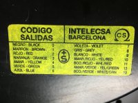
Here are the wire colors.
From transformer to PS board
From transformer to star nut (chassis ground)
From transformer to terminal / AC
Here are the wire colors.
From transformer to PS board
- Red
- Green
From transformer to star nut (chassis ground)
- Blue
- White
From transformer to terminal / AC
- Orange and Purple (connected same tab)
- Orange (not connected)
- Yellow and Black (connected same tab for power switch/AC plug)
- Gray (connected to power switch wire)
Attachments
First item on parts list
I will keep a current parts list on Post #1 once we get the list going, since I can edit it.
----------------------------------
Bourns trimmers (2 per board)
Since I haven't been able to get the MOSFETs off the heat sink, I can't remove the oem trimmers to measure. The only numbers on them are 500 and 938 ... I'm assuming "500" is ohm rating, and "938" is model number???
Here's what I found on Mouser that appears to be what I need. The oem trimmers are 3/8" wide.
3296P-1-501LF Bourns | Mouser
Last edited:
Sorry, there were multiple amps I was referring to. The Parasound doesn’t have input capacitors, the Wima parts were put into an older SAE amp I have here.
The old Parasound sounded much more clear after some parts swapping, many of the original parts were definitely there to help meet a price point, and may well have been beyond their time. The parts inside your amp looked similar in the pictures I’d found, and that’s why I mentioned it. The main filter capacitors are much larger in your amp however.
The transistors are likely held with heat conductive grease, and can be carefully pried away from the heatsink if you are confident that there’s no other fasteners.
Sorry, there were multiple amps I was referring to. The Parasound doesn’t have input capacitors, the Wima parts were put into an older SAE amp I have here.
Thanks for clearing that up. 🙂
The transistors are likely held with heat conductive grease, and can be carefully pried away from the heatsink if you are confident that there’s no other fasteners.
Not grease. These are definitely gray colored sheets. Mouser carries Wakefield-Vette which may be similar ... but I can't tell from the info they provide what I would need, especially thickness. If I saw it, I'd know, but trying to measure something that thin.
Oh, those are know as sil-pads, are a more production friendly method of thermally coupling.
I would leave them be since they don’t suffer from the issues that the grease has with age.
I would leave them be since they don’t suffer from the issues that the grease has with age.
Ah, sil-pads. Well, they are stuck pretty good on the heat sinks ... so depending on how I end up removing the MOSFETs from the heat sink, will determine if the pads are still in good shape. I have no idea if there was adhesive on these sil-pads.
Why are you removing the mosfets from the heatsinks? Just curious...
Those sil-pads get better transfer with age, and are not reusable either.
Those sil-pads get better transfer with age, and are not reusable either.
I thought it would be easier to work on boards this way. But you raise a good point. If I leave as-is, I don't have to worry about lining up the boards with the pins already in place.
Only you can decide whether or not you can safely make the parts swapping while still attached. Am not familiar with this amp having not worked on one myself.
I recall that one time I had made a temporary support to connect two large opposing heat sinks such that the amp case could be removed and not jeopardize the boards or outputs.
It was just a chunk of aluminum angle I think, with a couple holes to anchor to the heat sinks.
I recall that one time I had made a temporary support to connect two large opposing heat sinks such that the amp case could be removed and not jeopardize the boards or outputs.
It was just a chunk of aluminum angle I think, with a couple holes to anchor to the heat sinks.
True. I feel comfortable doing it, but your comment about leaving as-is, makes sense, and will help simplify the process.
I'm going by my hardware store for replacement hex head screws. I'm pretty sure they have the same screw ... they have a good selection. Why am I doing this? Well, some are rusty looking, and while I don't need to do this, I want to have this looking as good as I can inside.
I may also get new signal wiring from the inputs to the output boards to speakers. I don't think the AC wiring needs to be changed. However, I notice that some of the insulation on a few wires from the transformer don't completely cover the wire ... so I may try to fix that.
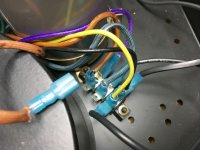
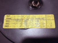
My biggest concern right now is that extra orange wire from the transformer. The tab connectors on these transformer wires hold really tight, so I can't imagine the wire just coming off. I don't have any pics of before I took this to the tech, and wondering if he pulled, or if it's been like that. I can't find any info on this, and the wire color code sticker just has numbers, and the other sticker on the transformer may provide the info I need, but I don't understand it.
I'm going by my hardware store for replacement hex head screws. I'm pretty sure they have the same screw ... they have a good selection. Why am I doing this? Well, some are rusty looking, and while I don't need to do this, I want to have this looking as good as I can inside.
I may also get new signal wiring from the inputs to the output boards to speakers. I don't think the AC wiring needs to be changed. However, I notice that some of the insulation on a few wires from the transformer don't completely cover the wire ... so I may try to fix that.
My biggest concern right now is that extra orange wire from the transformer. The tab connectors on these transformer wires hold really tight, so I can't imagine the wire just coming off. I don't have any pics of before I took this to the tech, and wondering if he pulled, or if it's been like that. I can't find any info on this, and the wire color code sticker just has numbers, and the other sticker on the transformer may provide the info I need, but I don't understand it.
Attachments

Heres a picture (somewhat)showing the errant wire.
B&K ST 202 plus modded Power Amp Photo #1352716 - US Audio Mart
If you can’t find the screws, you can always just polish up the ones you have I suppose.
B&K ST 202 plus modded Power Amp Photo #1352716 - US Audio Mart
If you can’t find the screws, you can always just polish up the ones you have I suppose.
Last edited:
Heres a picture (somewhat)showing the errant wire.
B&K ST 202 plus modded Power Amp Photo #1352716 - US Audio Mart
If you can’t find the screws, you can always just polish up the ones you have I suppose.
I just cleaned the screws down with WD-40 ... look good.
That amp is the later Sonata version with more circuitry on the PS board, and I can only see one orange wire ... and not where it's connected. That's one of the crazy things (to me) about this amp. It's a good sounding amp, but it obviously is not popular enough to find good info.
How is the wire in question terminated?
If you can’t find a home for it, and the amp works, then maybe keep it safely tied back somewhere. I was thinking it may be for 240v, or 120v on the primary side of the transformer, for another country perhaps.
You could just ohm out the various wires and see if there’s any correlation to the others.
Last edited:
The "extra" orange wire has a proper connection tab on it, like the others. Either B&K wanted it ready for different voltages, and it was just tucked in by the other wires that attach to the voltage terminal, or ???
From the pictures of the other models it appears that they all use the same transformer, maybe they had prepped all of them to be used in any model with connectors?
It's possible. I get the impression they were a very small company and needed to be efficient. That's the optimist in me. 🙂
Pictures of an output board in the works ... there may be a heat/burned area around one resistor. The resistor looks fine, but this is around the bias trimmer, so I'm going to be wondering if there is a different resistor that should go in that position.
I won't pull the other board out until tomorrow. It took me over an hour to slowly work on the legs. It appears that the pcb board became "glued" to the legs. So there was a little material residue from the pcb on most of the legs.
I did have one trace issue with two legs of the bias trimmer ... the solder trace on the center leg pulled up a little. I've had this happen once before, and it's still connected, no tear, so I'll just need to be super careful putting the new trimmer in.
They're not both orange wires. One of the wires is brown and the other is orange, they've faded with age. The picture of the ST202+ that Phase linked to confirms this.
According to your picture of the voltage rating plate it appears that the secondaries are probably wires #0,1,3 & #4,8,7. The center number in each series I would imagine should be the center tap. Maybe someone more savvy than me with transformers can take a look at the plate and figure out which wires should be the primary/secondary. If that doesn't happen your only recourse may be to find another ST-202 owner to send you a picture or two.
Myself before I begin touching anything inside of a piece of gear that I am unfamiliar with I take multiple pictures of the interior from various angles, wire routing, orientation of capacitors & components, connections, etc. If you do that in the future you'll minimize the chances of knocking something loose and not knowing where it attaches or if its unused. Even just poking around or dusting things off could result in a wire pulling loose or breaking at a solder joint and it can be a PITA to figure out where it went.
Also just so you know you cannot rely on the silkscreen on a board, you need pictures of the board before you disassemble it to verify that you've placed components in their proper orientation before soldering the new parts in. I have many times found production gear that has incorrect polarity marking on the board for a random component. The only way you'd know this is by checking the pictures prior to disassembly and comparing those pics to how you're placing the new components. Failure to do this will bite you hard!
- Status
- Not open for further replies.
- Home
- Amplifiers
- Solid State
- B&K ST-202 Plus :: hum