If I get a chance I'll take a picture of the insides of a preamp to show the construction.
Hello
Yes, it would be very instructive to see the insides of a preamp to show the construction.
Thank
Bye
Gaetan
Hello
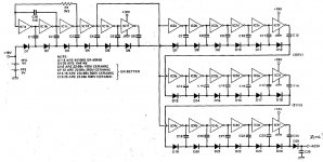
Q1= SFE793 ---it's a very hard to find data sheet and I can't find an easy to find equivalent, here a link where they say a little bit about that transistor:
5961-00-105-8867, SF51145, SFB9637, SFE793, F1151, FN1962, ITS3134 Official Source
Is there an easy to find equivalent for the SFE793 ?
This one are easy to find an equivalent Q2= BCY 57 --- bc109, 2n930
Bye
Gaetan
Last edited:
Here is a good start on finding an equivalent. If you have the old Siliconix book or a current Interfet book you can start matching the specs. The TO18 can is not critical.
Transconductance, pinchoff and gate leakage are the numbers to look at. You would find the right process and suitable general sort and select from there. Still quite the project.
1855-0020
N JFET
TO-18
500 mW max
Gfs=18mMho at Vds=20V
BVgds=40Vmin
Idss=50mA min 100mA max
Vp/Vgs(th)=10V max
Igss=500pA max
Hello
Maby 2N4856 or 2N4857 for Q1 ?
Thank
Bye
Gaetan
2N4856 looks good and it's not even unobtainium. You would want to check the noise. Here's a cute HV supply that costs almost nothing, You could probably get 200V at the end with only one 9V battery.
Attachments
Hello
In the Vishay 2N4856 data sheet the noise are 3nv at 1khz, it's quite good.
But 1 G ohm resistors will be hard to find.
Thank
Bye
Gaetan
In the Vishay 2N4856 data sheet the noise are 3nv at 1khz, it's quite good.
But 1 G ohm resistors will be hard to find.
Thank
Bye
Gaetan
Attachments
Last edited:
Hello
I've just look at the Vishay web site and they don't made anymore the 2N4856
Bye
Gaetan
Use octopart.com, there are NOS 2N4856 listed at <$3, and mouser has 1G 1/4W metal film resistors at .... .666$. I found octopart to usually be right on stock numbers.
Hello
I've found 2N4391(92) and PN4391(92) at Mouser for very much lower price than the 2N4857.
I would buy the Jfet and 1 G resistor at Mouser to pay only one shipping cost.
Is those 2N4391(92) and PN4391(92) can be as good as the 2N4857 for the HP mic preamp ?
http://www.linearsystems.com/datasheets/2N4391.pdf
http://www.fairchildsemi.com/ds/PN/PN4392.pdf
Thank and Merry Christmas to all the guy's
Bye
Gaetan
Last edited:
Hi Scott,
I thought the max supply was on the order of +16 VDC for one. Maybe some could be pushed to +18 volts abs max, but I wouldn't want to depend on that.
Please help a tech's crashed mind as he attempts to digest this idea. Had anyone else posted it, I'd likely be telling them it is extreme and wanton cruelty to a poor defenceless CMOS chip. The thing that I can see happening is the charge through the cap is all the chip experiences, but I'm worried about what is going on with the initial peak current, energy increasing as the square as the voltage goes up and all. Peak currents might be the undoing of this cool circuit.
Otherwise, really cool circuit. Thank you for posting it.
-Chris
Hi Gaetan,
The extreme resistances I have seen were encased in glass. They were pretty long too. I once had some 70 K Meg (yes, that was the value) for Geiger counters. As I recall, the resistors inside the glass were painted red. This had to be for voltage breakdown, but also getting the leakage path to be long enough. Normal humidity might very well decrease the value of those resistors, and a finger print would be your undoing.
Teflon standoffs are used to eliminate the "K effect" from PCB material as well as extend the leakage path as previously mentioned. The PCB material would become a capacitor, presenting a loss and doing funny things with charges at those impedance levels. Noise would be expected as a result - never mind distortion with a weird quality. With the Teflon standoffs, conductors now form a lower value capacitor using air as the dielectric. That means a good capacitor. Since the "K" of air is only slightly higher than that of a vacuum, the resulting capacitance is lower than you would get with a material between conductors. They do offer PCBs with a Teflon substrate, but you don't want to know how much. Actually, I don't even know how much that stuff is. It would be perfect for Mic, RIAA or general signal preamps. The main use is supposed to be for RF circuits I think.
If we don't post together before then, Merry Christmas to you as well. Do you think there will be snow in Quebec for Christmas?? 🙂
Hi Scott,
Thinking along this line, would this be the reason for the small sound differences between the DIP-8 and metal 8-pin packaged op amps? To the best of my knowledge, the die is identical, the bond wires might be the same material, so that leaves the lead frame and material it is encapsulated with. The DIP-8 lead frame would also travel a much greater distance inside the material.
Personally I have never compare the two. I have no expectations at all beyond hearing other reports on this. You be da man to ask if there is anyone around here that could answer.
-Chris
Hello Chris
It could be fun to try to made some diy 1 G ohm resistors and put arround it some silicone glue.
I remember many comments from various diyers and audiophiles about a better sound from metal 8-pin packaged op amps. Yes maby the shorter wires inside the metal can, but maby also because the metal can do a total isolation from external rf noise.
I live in mountain in the Laurentides, here we have 2 inches of snow with ices everywhere on the snow and on the road.
Thank and Merry Christmas to you to.
Bye
Gaetan
Last edited:
Hi Gaetan,
I figured you would have snow. Believe it or not, we don't have any. It's fairly warm outdoors still. Let's see what colour Christmas we get.
-Chris
I figured you would have snow. Believe it or not, we don't have any. It's fairly warm outdoors still. Let's see what colour Christmas we get.
-Chris
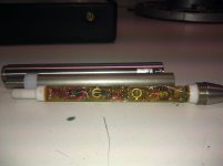
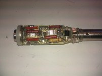
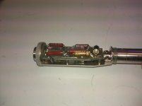
Photos of mike preamps
Here are pictures of the inside construction of the HP 1/2" mike and a B&K 1" tube mike. I could not figure out how to open the B&K preamps I have and the open ones I have are not here. The B&K has the ntube under the PCB. You can almost see it in the side view. Enjoy.
Here are pictures of the inside construction of the HP 1/2" mike and a B&K 1" tube mike. I could not figure out how to open the B&K preamps I have and the open ones I have are not here. The B&K has the ntube under the PCB. You can almost see it in the side view. Enjoy.
Attachments
I realize this is an Old Thread, but just curious if the B&K 2671 could be made running ?
Or if anyone ever has seen a schematic ? From there the required supply could most likely be determined.
Thanks!
Or if anyone ever has seen a schematic ? From there the required supply could most likely be determined.
Thanks!
Is this what you are referring to? https://www.bksv.com/en/products/transducers/acoustic/microphones/preamplifiers/2671
That family of preamp/interfaces is quite different from the older stuff. All you need is a 28V supply and it modulates the output current. No mike bias so you need prepolarized mikes.
That family of preamp/interfaces is quite different from the older stuff. All you need is a 28V supply and it modulates the output current. No mike bias so you need prepolarized mikes.
Thanks for the response. Yes, that's indeed the one & has the pre-polarised 4155 capsule.
I found this, so I'll build a 4mA current source Project 134
I guess I can testdrive it (checking for basic functionality) simply by that 28V-osh voltage and a resistor & AC-coupling cap.
Was a bit surprised I couldn't find any relevant schematics on the interweb, they seem well guarded.
Best regards
B&K has morphed like most of its competitors into a more closed operation. I doubt any of these things get fixed today. In the corporate world they just get replaced. The current mode interface has become quite common and makes it easy to move from transducer to transducer in different applications. With a "small" sacrifice in performance.
Nice link with lots of useful info.
Nice link with lots of useful info.
B&K has morphed like most of its competitors into a more closed operation. I doubt any of these things get fixed today. In the corporate world they just get replaced.
I see, so less/no need for service documentation. The simplest 1 channel interface for such a mic-pre does ~$500 2nd hand (asking price) so that makes it a no-brainer, as in: DIY a 4mA current source myself.
BTW, note that one of the suggested supplies (WB-1372) 'does' 3mA +/-20%, so less than the assumed to be the typ value of 4 mA.
FWIW, I assume it might be related that this WB-box is battery-powered.
The current mode interface has become quite common and makes it easy to move from transducer to transducer in different applications. With a "small" sacrifice in performance.
Curious to learn, which performance-sacrifice ?
Nice link with lots of useful info.
The ESP-site a valuable resource!
For convenience, several Projects have also PCBs available.
Best regards
A battery powered version would make a lot of sense. It would not be hard. I would use a cheap DC-DC converter from China + a Lipo battery. Then probably a depletion mode mosfet plus a selected current diode for the current supply. Supply current does have an effect on the output voltage. With the B&K mikes they don't need gain so much less effect on the output. The output is high enough that you can use a follower inside and get a low output Z.
LM2587 DC-DC Boost Converter 3V-30V Step up to 4-35V Power Supply Module MAX 5A | eBay
I could sketch out the rest later if you want.
LM2587 DC-DC Boost Converter 3V-30V Step up to 4-35V Power Supply Module MAX 5A | eBay
I could sketch out the rest later if you want.
- Home
- Amplifiers
- Power Supplies
- B&K microphone power supply - help needed