R4 and R5 values are swapped on the schematic. The values in the board are correct.
R14 is 100R on the board which is correct. The 0R link on the board really is a link. It's shown on the placement drawing.
As mentioned in an earlier post the typical supply rails for this type of amp are 35v. That being the case the LED current would be about 3.3mA and the current through TR1 would be about 1.2mA which is basically what Rick has said.
Sid
Still confused so 0v means there all linked together? If case then found other 10k which is on complete opposite side of diagram linked to a 12v zener and the vu meter circuit. I cannot find another 47k on there at all but it’s in series with the other. Even adding together there’s no matched resistor of that value. I can find my way round spaghetti junction point to point wiring but this has thrown me for sure ha.
Yeah 100r not thrown me just how it’s laid out and extra resistors in circuit but not on schematic. The other diagram does not even show there is an R4?
So in essence nothing needs changing just getting the circuit biased and changing the resistor values Rick has said if I’m not getting the voltage amp readings to be expected.
Christ I thought the 10mm led was in height not diameter be like a mini light bulb in there ha ha.
On the placement drawing the rectangular TR1 is really R4.
On the schematic, connections labelled 0V are all connected together.
R19 in the VU meter power supply section is not directly connected to R4 (10k).
I don't know what you mean when you mention the 47k resistor. There is only one (R3)
Sid
On the schematic, connections labelled 0V are all connected together.
R19 in the VU meter power supply section is not directly connected to R4 (10k).
I don't know what you mean when you mention the 47k resistor. There is only one (R3)
Sid
Thanks Mark T and sidsparks .. As usual, your wording is better than mine.
Cheers, Shockhazard -- hope you're not looking for a mate for R19! There is a lot of pairing and symmetry to this design, but that isn't one.
Each is charged with supplying a small current to a voltage reference - completely non-critical.
Hope your kitty is on the mend.
Cheers, Shockhazard -- hope you're not looking for a mate for R19! There is a lot of pairing and symmetry to this design, but that isn't one.
Each is charged with supplying a small current to a voltage reference - completely non-critical.
Hope your kitty is on the mend.
Thanks guys.
No no mate with R19 ha ha. I need a 12v tap of it though.
Yes there is only one R3 but if you look at drawing post 80 you will see there are two 47ks in series but only R3 listed as 47k there's no reference anywhere on the actual circuit of R3 being in series with another 47k. Also if you can blow up the picture you should be able to see the two of them in series. Hopefully the colour codes are visible if not let me know and I'll take a micro pic of them. They have a pink ring on them so can't miss them. Have a look and you'll see what I mean. That's why I'm scratching my head ha ha.
She's purked up a bit Rick but been going on long time and I managed to get hold of the medical reports which show issues but they kept telling me nothing wrong so now there bending over backwards to address it all now. Wonder why? Sue the crap out of them. Dont trust the medical profession at all even I was not told about spread to bowl, throat, spine etc. Only know because I can now access my medical records it all comes out now. Ha well ya gotta laugh.
But thanks for asking.
Those MF100 modules were plug and play the only thing needed for them to work was a power cord (toroid was part of the module ) with a switch and the input and output connected the VU was not needed for operation.
So assuming the modules where in working conditions (Leds where lit up on first pictures) I don't see why all this is even necessary.
So assuming the modules where in working conditions (Leds where lit up on first pictures) I don't see why all this is even necessary.
Well for me it's been a good learning curve having not worked on these so think it's been worthwhile and plenty of reference material.
But it goes to show you can't just trust the schematic which is very important. If I was changing and pulling things according to schematic I'd be in trouble plus getting rail voltages above 64/65 volts above the rated 63v caps not good in my own personal opinion.
So I'd disagree to be honest. Plus the outputs getting hot with no load! There's obviously something wrong. But my personal opinion.
I won't destroy them. Think got enough background info now from everyone so got good idea where I'm going now. What voltages should be what the currents should be etc. What should connected to what etc So feel pretty confident. I'll take the readings then post and hopefully there in the ball park figure.
But I agree to get originals not copies near on impossible. I've seen some which look original and advertised as NOS but they look like they've been pulled from an old unit. Plus 20 quid plus each and not knowing if there copies or used. So I won't blow em for sure. If I do I'll eat my 10mm leds and plug myself in.
But I agree to get originals not copies near on impossible. I've seen some which look original and advertised as NOS but they look like they've been pulled from an old unit. Plus 20 quid plus each and not knowing if there copies or used. So I won't blow em for sure. If I do I'll eat my 10mm leds and plug myself in.
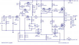
Please don't expect any bias recommendations from the CircuitsToday schematic in post 90, or its write-up elsewhere, to apply to your 2SK135 / J50 ! Despite the uncanny similarities all the way up to the output stage, an IRFP240 / 9240 output stage is a completely different animal from your lateral MOSFETS.
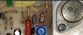
Did one of your driver transistors blow its top?
Cheers
Did one of your driver transistors blow its top?
Cheers
Attachments
Don't worry Rick just interested me that its ground reference points as opposed to 0v to be honest not quite sure why I put it there pills again ha ha.
Told ya those are not the originals 3 of them are marked like that but one original left in the one behind it to left. Hence bought some nos ones so I can replace all four as the ones I have are all matched same date codes and manufacturer.
Told ya those are not the originals 3 of them are marked like that but one original left in the one behind it to left. Hence bought some nos ones so I can replace all four as the ones I have are all matched same date codes and manufacturer.
Did one of your driver transistors blow its top?
Cheers
That's TR5. TR6 also looks like it's blown it's top. The other channel looks ok.
Sid
Ye-e-a-ah, .. Um ..
Sorry to disappoint -- that's a good starting point to matching -- they're probably going to be reasonably close. But there can still be enough difference to slightly upset a largely balanced circuit like this. Nothing that won't surrender to a judiciously placed trimpot, or two. But check back in here, 'cause there are some lousy locations / techniques, too.
Manufacturers often do their own matching for such gear. I usually order 10 of anything that I need a pair of, and it generally saves time.
Cheers
Shockhazard said:.. the ones I have are all matched same date codes and manufacturer.
Sorry to disappoint -- that's a good starting point to matching -- they're probably going to be reasonably close. But there can still be enough difference to slightly upset a largely balanced circuit like this. Nothing that won't surrender to a judiciously placed trimpot, or two. But check back in here, 'cause there are some lousy locations / techniques, too.
Manufacturers often do their own matching for such gear. I usually order 10 of anything that I need a pair of, and it generally saves time.
Cheers
I've got 6 of them so I'm sure the others are fine on other module as you mentioned I'll pull em and test out of circuit. Like I said got this gear off a DJ and this was used but you can see the original caps blew as remnants all over pcb.
Plus the dust caps blown out on the 100 watt pa speakers and coils where misaligned think speaks for itself the unit and speaker obviously well overloaded.
Will do.
Many thanks Chris
Plus the dust caps blown out on the 100 watt pa speakers and coils where misaligned think speaks for itself the unit and speaker obviously well overloaded.
Will do.
Many thanks Chris
Meant got 8 of them. 6 of the 2sb not sure life span of these but all the amps where last PAT tested in 1980 so probably been in storage sine 1982. So components are all well over 40 years old now.
Plus having been driven probably near max during there lifetime sure thats put a strain on them all.
But be interesting to compare to the valve's.
The next one I think you'll find interesting thats mid 70s huge dual transformer and module twice size of these ones. Plus the Vortexion fet 50/70 caps need doing on that one but not able to find a switch to run the 100v line down to domestic speaker use. Sure its there but get this one done first.
- Home
- Amplifiers
- Solid State
- b k electronics mosfet 100 watt modules