This has helped very kind of of BK electronics. I’m assuming the bias will be set ccw as opposed to cw.
Hello Chris
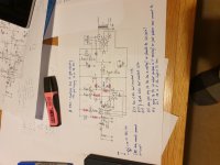
BUZ900 = K135
BUZ905 = J51
R13 is 6K8
R15 and R16 are gate resistors and were raised to 470R for the BUZ900 and 905 for the K135 and J51 then the gate resistor are ok at 270R
Main rails are 58 - 0 58 DC
PR1 is the setup for quiescent current and this will be quite low 10 to 100 ohms
Hello Chris
BUZ900 = K135
BUZ905 = J51
R13 is 6K8
R15 and R16 are gate resistors and were raised to 470R for the BUZ900 and 905 for the K135 and J51 then the gate resistor are ok at 270R
Main rails are 58 - 0 58 DC
PR1 is the setup for quiescent current and this will be quite low 10 to 100 ohms
Forgot all nos Philips transistors came today at last plus they are all from the same batch and the hfe readings all check out okay so I’ll pull those ones that had been changed out plus the original left in then I’ll have nice match. I’ll also pull the 10ks and put new 6.8ks in. Then just wiring up and setting up bias. Oh and new 10mm LEDs too might as well go the whole hog as they say. I’ll leave the other and see if any there’s any difference in sound.
Getting excited now ha ha.
Me poor cat not been well and me so another trip to vet tomorrow getting a bit tiring. Had me COVID jab Saturday blimey got a whacker of a headache and the sweats all passed now.
Getting excited now ha ha.
Me poor cat not been well and me so another trip to vet tomorrow getting a bit tiring. Had me COVID jab Saturday blimey got a whacker of a headache and the sweats all passed now.
Just accidentally smoked the post I had spent all yesterday afternoon and evening (intermittently) working on, with a 'pilot error'. 
Sorry for the delay -- and that was already delayed enough. Will see if some 'truth serum' can help this old brain recall some of it and post later ..
Don't remember who said it (and I'm probably mis-quoting anyway), but "Getting old is not for the faint-hearted -- even if it is better than the alternative."
Regards
edit: One thing I can mention: +/-58V rails puts the current through that poor, overworked green LED, at 46½mA -- way too high. That's guaranteed to damage a 1980's LED.
Last edited:
Don't know which plural '10ks' you're talking about, but the bigger problem is the R4 value. A few hundred uA would be plenty for the CCS to function; go ahead and make it a couple/few milliamps just so the LED lights, and you're on the crisp part of the knee.
Cheers
Cheers
Last edited:

Leaving one end of PR1 floating is asking for trouble -- likely well into the future, but nonetheless serious trouble.
I would connect the floating end to the wiper. That way an intermittence (bound to happen sooner or later) won't cause momentary saturation conduction by the outputs.
Even better would be add a fixed resistor in parallel. This is to reduce the adjustment range to maybe 15 or 20% higher than the desired value, once you've found what that is. Likely values might be 1k2, 1k5, or 1k8.
Cheers
Last edited:
Cheers Rick a lot to take in there yes the 50 odd volts I thought was rather high for 100 watt module. From what I’ve read it’s around 35. I switched that resistor to a 10k as per schematic as it has a 6.8k there which as said had burnt the board so getting way too hot.
So you’ve lost me on R4 and R5 sure you said R5 need reducing the 10k one. But saying R4?
Yes looking at trimmer has thrown me a bit as looking at other schematics it’s slightly different setup. Anyhow I’ll plod at it and digest all that info.
Yes your right about old age ha ha mind you I’m only 56 and brain like a sieve but my excuse is too many drugs ha ha.
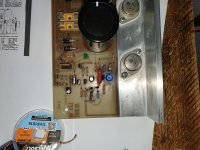
Pic with some info.
Solid state no no no not my cup of tea I'm afraid. I'm a valve amp guy can't replicate that sound although these mosfets are supposed to be near the mark hence the interest to get modules up and running like new. Got couple others as well so can do some comparisons.
Interesting circuitry but basic but complicated at the same time. So for now can't say I'm a fan of mosfet amps as not really tested one yet.
Solid state bit clinical in sound reproduction vintage and new gear. Valves on other hand warm transparent and good solid allround sound reproduction. For me like having headphones on sounds you usually don't hear flow through the speakers and pick up those detailed lows and highs which are lost with Solid state gear. But thats just my personal opinion.
Attachments
R4 provides all the current for the LED and TR1's Base. The latter only eats a few dozen micro-amps, and the LED only needs a few mA, to get on the 'crisp' point of its V-A curve.
Any green LED, forward biased from a 58V rail by a 1200 ohm resistor, will see a current of 46½ mA -- at least initially.
Swapping it and R5 would set the LED current at 5,6 mA -- much more reasonable and plenty to hold TR1's Base at 2,2V. Even 22k, 27k (2,1mA LED current), or 33k (1,7mA) would be plenty and just fine.
Fitting the 1k2 (the original R4) between TR1's Emitter and the '+' rail, puts ~1,6V across it providing a 1,3mA current for the input differential pair -- much healthier.
I have known schematic draftsmen, and have been one -- mistakes do happen. Sometimes the equipment works anyway; sometimes it's more failure-prone, sometimes it just sounds crappy; sometimes it still sounds OK. There have been pieces built and sold, for which no schematic was provided, because the designer thought it was so darn clever that it needed to be kept secret -- *proprietary*.
Plenty of possible explanations. Best to save brainpower for making it right, than to spend it trying to sort how it got the way it is.
Cheers
Last edited:
Working from the last two blue, hand-written notes from the post 73 pic, my explanations on R5 and R4 aren't good enough!
First, confirm that the LED has ~2,2V across it. (*) You can leave R5 out of the circuit and power it up. That will leave everything up to the outputs off, so no harm will come. Just don't measure the output offset -- it won't mean a thing because it will only be leakage currents.
If R4 is still 1k2, take it out. Replace it with a 15k, 22k, 27k, or 33k. That may seem drastic, but so is powering a 1980's LED with 46 milliamps!
Once the voltage at TR1-Base is confirmed to be ~2,2V below the '+' rail, you can entertain values for R5. There are different theories on how much current to run your input pair (Tr2, TR3) on, but most fall in the 0,6 to 2mA range. The Emitter of TR1 will be held firmly at ~1,6V (if the LED is behaving/not damaged), so the resistor that used to be R4 - the 1k2 - will actually be a pretty nice 1,3mA -- a good starting point.
Then we'll be ready to address the issues in the next stage.
Regards
*) I'm betting that it has been 'stretched' by the overcurrent, and its 'knee' is now too soft.
Last edited:
Will do Rick give it go tomorrow. Been tied up with me cat not been well for while now but vet's got his finger out of his ar.. realising she's not well taken 2 bloody years. Bad enough looking after myself let alone an unwell cat. But she's settled down so I can hopefully crack on and not end up distracted. Got everything out in morning to crack on then it's running round after her. So not getting anywhere.
Did think that was all bit wrong and like say getting over 64v on the rails worried me knew that was not right on this type of circuit. Still learning but good fun. Can't believe that the perfect amp circuit so keep it hush hush. Is there a perfect amp circuit? I Don't think so. Got some new 10mm LEDs so swap out put new ones in but your right the originals are dim. One has a chip in it as well. Plus leads on them are all overheated scorched.
Don't know what ya mean knee too soft? Never come across that before.
how healthy is the LED? It should be cranking out a lot of light powered by the 1k2 to ground. And 35 mA is a lot for a 1970's LED. If it is not extremely bright, it is almost certainly failing.
1970's LEDs were never bright by any stretch of the imagination, certainly not green ones - modern LEDs are literally 100's of times brighter for the same current, there was no quantum-well tech back then, so I'd expect the LED to look very dim even at 35mA if its original - but yes, 35mA is too much, 20mA was usually the absolute maximum current.
Thanks for that that cleared up then. I was expecting them to be burning bright. But I keep forgetting how things have moved along.
Oh well ill have a bright green internal chassis now. Ha.
Yeah the red and green all seem to be around 20/25mA other colours slightly higher. Who'd think an LED being an essential part of the circuit. Although valve gear same with pilot bulbs. So no changed much in that sense.
Oh well ill have a bright green internal chassis now. Ha.
Yeah the red and green all seem to be around 20/25mA other colours slightly higher. Who'd think an LED being an essential part of the circuit. Although valve gear same with pilot bulbs. So no changed much in that sense.
L
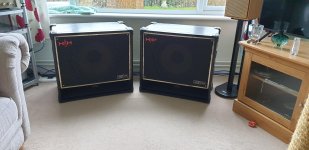
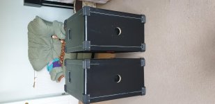
Here's speakers ill run it through complete refurb they where a complete mess dust caps blown out damp damage to the bottom cabinets veneer all torn but was happy with end results. I ran them through my quad oh my God unbearable beautiful sound but whole room and even my body was vibrating could only bear 5 minutes and that was only two notches on volume.
Here's speakers ill run it through complete refurb they where a complete mess dust caps blown out damp damage to the bottom cabinets veneer all torn but was happy with end results. I ran them through my quad oh my God unbearable beautiful sound but whole room and even my body was vibrating could only bear 5 minutes and that was only two notches on volume.
Attachments
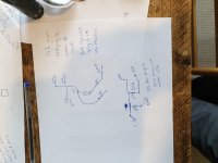
Right that schematic is not for this module at all. 1k2 does not goe to 0v it goes to another 10k do you have a 20k on each leg of the led then off to 2200pf cap other part 1k2 goes to gate of 2sa as shown.
Plus you also have 47k going to 0v but its in series with another 47k both of which go to the 2sa again but there's no other 47k listed on that schematic. Have a look plus there is no other 10k listed on it either.
Pics attached. Definitely not the schematic for this one. Well how it's looking to me have a look at the tracks on module second picture. So I think this schematic is either unfinished or parts omitted for some reason. Majority of it matches.
No wonder I'm getting confused on this one as I'm looking and things not tallying up.
Attachments
- Home
- Amplifiers
- Solid State
- b k electronics mosfet 100 watt modules