gupsta,
A boost transformer is a very good idea.
Many 5VAC transformer secondaries are rated to insulate 1000V or more from primary to secondary.
The secondary is put in series with the power mains, to get 5VAC more than the 119V . . . 124V
You have to get the phase right, or it will decrease the series voltage by 5V, and give only 114V out.
Make sure the transformer is overrated, or it will have a crest factor of its own that will get in the way when the peak rectifier current happens every alternation.

As you said, you checked all voltages at Old House 6 years ago. How long and how often does the RECT TUBE 5V4G work in the amplifier? If the tube becomes old, the resistance will increase and cause DC output to decrease. Check the working conditions of both the RECT tube and the first few e-caps are closely connected to the output transformer. Warning------ beware high voltages and discharge e-caps those are required, before handling and checking. It is dangerous if you don't do this. Usually 5% tolerance of AC supply variation is acceptable. But huge dropping at your B+. Filament voltages are reasonable. Aren't they?
Crest factor as point out by 6A3sUMMER gets my vote.
Crest factor (THD distortion) can in some locations be pretty significant.
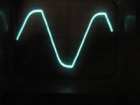
I lived for a short time on Vancouver island and the power from the plug looked convincingly like a square wave, there was so much flat topping.
I though at first I had made a measurement error, it could not actually look like that? Really!
It resulted in the DC level for B+ being low and the filament RMS voltage being high on vintage tube equipment I had.
Modern day power distribution systems can have a variety of strange loads that cause flat topping. As well huge DC to AC converters for wind, solar and ultra high voltage DC distribution cables tend to have higher levels of THD.
iEEE standard for power systems seems to recommend 5% or less voltage distortion in the power system. This is a lot of flat topping.
The past days of nice SIN waves from clean rotary generators being fed into largely resistive loads are long gone.
Crest factor (THD distortion) can in some locations be pretty significant.
I lived for a short time on Vancouver island and the power from the plug looked convincingly like a square wave, there was so much flat topping.
I though at first I had made a measurement error, it could not actually look like that? Really!
It resulted in the DC level for B+ being low and the filament RMS voltage being high on vintage tube equipment I had.
Modern day power distribution systems can have a variety of strange loads that cause flat topping. As well huge DC to AC converters for wind, solar and ultra high voltage DC distribution cables tend to have higher levels of THD.
iEEE standard for power systems seems to recommend 5% or less voltage distortion in the power system. This is a lot of flat topping.
The past days of nice SIN waves from clean rotary generators being fed into largely resistive loads are long gone.
The 3 measurement effects of that kind of a Power Mains waveform:
You will get One reading of ACV if you use an old style analog VOM. It responds to the Average of one alternation in only one direction.
(Half Wave rectification)
You will get a Different reading of ACV, if you use a VTVM or TVM. Those meters respond to the Peak voltage; usually in one direction only (half wave rectification).
You will get a Third reading of ACV, if you use any True RMS meter. Those meters respond to the integral of the Root Mean Square, over time.
The point is, you get three different answers of VAC, when the waveform is distorted.
But if the Power Mains has a perfect un-distorted sine wave, all 3 types of meters will read exactly the same ACV.
My Tektronix digital oscilloscope has a software measurement feature called Cycle RMS, that reads out True RMS Voltage (ACVrms) of one cycle.
It also can measure RMS across the whole screen, regardless of how many cycles or other waveforms are across the screen.
For interest I made up a spice sim of a SINE wave the easily meets the IEEE standard for 5%.
Total THD is 4.1%, well below the required 5% THD maximum.
The third harmonic is below 3% as required and all other harmonics are below 2% as required.
The result is pretty nasty looking yet this is perfectly acceptable power for your neighborhood wall outlet.
Both wave-forms represent a true 120V RMS as show by spice in the first picture
Note in the second picture the clean 120V has the correct peak voltage of 169V and the nasty one peak is only 158.8V or about 6.5% low.
So you DC supplies will all be about 6.5% low assuming the line voltage is spot on correct RMS voltage.
If the RMS line voltage is a bit low, down goes your DC supplies more yet.
Conclusion....Filament and DC voltage levels in vintage designed power supplies can be crap shoot with today's power lines.


Below is the harmonic makeup.
Total THD is 4.1%, well below the required 5% THD maximum.
The third harmonic is below 3% as required and all other harmonics are below 2% as required.
The result is pretty nasty looking yet this is perfectly acceptable power for your neighborhood wall outlet.
Both wave-forms represent a true 120V RMS as show by spice in the first picture
Note in the second picture the clean 120V has the correct peak voltage of 169V and the nasty one peak is only 158.8V or about 6.5% low.
So you DC supplies will all be about 6.5% low assuming the line voltage is spot on correct RMS voltage.
If the RMS line voltage is a bit low, down goes your DC supplies more yet.
Conclusion....Filament and DC voltage levels in vintage designed power supplies can be crap shoot with today's power lines.
Below is the harmonic makeup.
Code:
FOURIER COMPONENTS OF TRANSIENT RESPONSE V(OUT)

HARMONIC   FREQUENCY    FOURIER    NORMALIZED    PHASE        NORMALIZED
    NO         (HZ)     COMPONENT    COMPONENT    (DEG)       PHASE (DEG)

     1     6.000E+01    1.695E+02    1.000E+00   -7.207E-03    0.000E+00
     2     1.200E+02    8.599E-05    5.073E-07    8.671E+01    8.672E+01
     3     1.800E+02    5.038E+00    2.972E-02   -2.136E-02    2.600E-04
     4     2.400E+02    7.042E-05    4.155E-07    1.009E+02    1.009E+02
     5     3.000E+02    3.543E+00    2.090E-02    1.800E+02    1.800E+02
     6     3.600E+02    1.566E-04    9.237E-07   -8.991E+01   -8.987E+01
     7     4.200E+02    2.961E+00    1.747E-02   -5.047E-02   -1.924E-05
     8     4.800E+02    1.257E-04    7.415E-07    8.755E+01    8.761E+01
     9     5.400E+02    5.059E-01    2.984E-03    1.799E+02    1.800E+02
    10     6.000E+02    2.414E-05    1.424E-07    1.148E+02    1.149E+02
    11     6.600E+02    7.092E-01    4.184E-03    1.799E+02    1.800E+02
    12     7.200E+02    1.454E-04    8.576E-07   -8.785E+01   -8.777E+01
    13     7.800E+02    8.148E-01    4.807E-03   -9.357E-02    1.211E-04
    14     8.400E+02    1.456E-04    8.592E-07    8.838E+01    8.848E+01
    15     9.000E+02    3.307E-01    1.951E-03    1.799E+02    1.800E+02

TOTAL HARMONIC DISTORTION = 4.096919E+00 PERCENTWhile some of the details are way over my head I appreciate the time and effort that you all have put into diagnosing my problem. Guess I need to move back to my old hood!
No electrolytes in the amp and yes I take precautions always. Filament voltages are reasonable.As you said, you checked all voltages at Old House 6 years ago. How long and how often does the RECT TUBE 5V4G work in the amplifier? If the tube becomes old, the resistance will increase and cause DC output to decrease. Check the working conditions of both the RECT tube and the first few e-caps are closely connected to the output transformer. Warning------ beware high voltages and discharge e-caps those are required, before handling and checking. It is dangerous if you don't do this. Usually 5% tolerance of AC supply variation is acceptable. But huge dropping at your B+. Filament voltages are reasonable. Aren't they?
seems normal to me...B+ dips a lot in a tube amp depending on the dc resistance of the ptx primary and secondary and any resistor or chokes along the B+ line, as long as you get 250vdc @60ma 2A3 plate voltage, then you hit the sweet spot for that tube..Measurements tubes installed:
120VAC on the PT primary.
741VAC (secondary) cross the plates of the 5V4G rectifier.
2A3 - 2.35VAC across filaments.
6SF5 - 6.59VAC across filaments.
5V4G - 4.86VAC across filaments.
Is it normal to have this 9VAC drop from the spec’d 750VAC PT?
1. Safety First!
The B+ circuit should have bleeder resistor(s).
Add up the capacitance of all the filter capacitors, call that Ct.
Suppose Ct is 200uF.
R x Ct is the RC time constant.
As you turn the amp power off, remove the power cord (you can slip and touch the IEC socket).
A 200uF cap and a 50k power bleeder will discharge the B+ to 37% of its original voltage in 10 seconds. 450V becomes 166.5V in 10 seconds, and becomes 61.6V in the next 10 seconds. If it takes you 30 seconds to get the bottom cover off of the amplifier you are safe.
Prevent the "Surviving Spouse Syndrome".
2. Hopefully this will make some power characteristics clear:
If an amplifier is designed for 120VAC, and if the power transformer is used below its VA rating, then whether
The power mains are 120Vrms pure sine wave,
Or
120Vrms with 5% clipping . . .
The AC powered filaments will be heated exactly the same. That is why we call it 120Vrms. RMS is the heating power.
A conservatively rated power transformer will still put out 6.3Vrms.
However, the B+ voltage changes, because of the lower peak voltage of the 5% clipped wave.
- Home
- Amplifiers
- Tubes / Valves
- B+ dropped 15%