Hi All -
This design finally went live:
https://www.bcspeakers.com/media/W1siZiIsIjIwMjEvMDgvMDMvMTBfMTRfMDJfNTU4XzIxNURDWC5wZGYiXV0
I wonder how it would compare to the Danley Signature Series or even the SH50s.
Cheers,
Ian
This design finally went live:
https://www.bcspeakers.com/media/W1siZiIsIjIwMjEvMDgvMDMvMTBfMTRfMDJfNTU4XzIxNURDWC5wZGYiXV0
I wonder how it would compare to the Danley Signature Series or even the SH50s.
Cheers,
Ian

Quick reflection, it seems a bit underutilised with regards to enclosure volume, the entire compartment housing the horn is not used correct? A different orientation/loading of the woofers could potentially have made use of this volume and thereby keeping their performance while decreasing the overall size of the design.
Just speculating a bit, there might be good reasons for not wanting to do so, it is a big horn, with large surfaces that might not fare all that well if exposed to the internal cabinet spl.
There may also be other reasons for shaping the front of the cabinet the way they have, a slight vibration cancellation for the woofers perhaps, alignment of acoustical center's, just guessing.
Last edited:
I had to do some digging. It can be found in the suggested designs: Suggested Designs - B&C Speakers
I've attached their PDF here for reference.
I've attached their PDF here for reference.
Attachments
I'm curious about how they managed to got the horn to load evenly from 400Hz to well above 10kHz, that a coaxial CD can generate the bandwidth is a feat in it self but perhaps a bit easier to understand, but a horn, a single horn that covers that bandwidth is more dificult to grasp.
That is if the horn actually works as a horn throughout the entire bandwidth, eitherway it is most impressive, and I hope this catches on and that celestion puts out something similar, then RCF, Beyma, faital etc..
It is a very clever way to get decent coverage high output pointsources without having to go full on turbosound flashlight (still a reference in my book btw)
The Celestion Axoperiodic loaded on a suitable horn performs a similar feat. By removing the x-over in the 'critical vocal range' -as the saying goes - the result is a clean and very 'unlike' horn sound. Those horns are very big, though - the size of the overall cabinet in Bennett Prescott's video doesn't really bring across þhe huge size of the beast.
I'm curious about how they managed to got the horn to load evenly from 400Hz to well above 10kHz, that a coaxial CD can generate the bandwidth is a feat in it self but perhaps a bit easier to understand, but a horn, a single horn that covers that bandwidth is more dificult to grasp.
That is if the horn actually works as a horn throughout the entire bandwidth, eitherway it is most impressive, and I hope this catches on and that celestion puts out something similar, then RCF, Beyma, faital etc..
It is a very clever way to get decent coverage high output pointsources without having to go full on turbosound flashlight (still a reference in my book btw)
the horn has a diffraction slot that's hard to see in the PR images 😉
A friend notified me about this project, and as fun as it looks, there are some difficulties to get this to play together right away that I noticed. I know the product range of B&C/18s pretty well, and this is absolutely not the combo of drivers I would have selected. Probably the two biggest issues here are the passive crossover on that coaxial compression driver, and the use of subwoofer drivers as midranges. The passive crossover will be modulated by the impedance of the compression driver, we see the same thing on all attempts on pro line array boxes with coaxial compression drivers and passive XO. Active XO works like a charm, but I think we have yet to see a successful passive XO for such an application, and I would not be surprised if this is not an exception either.
For the woofers, I would like to point out the high inductance. Besides the inductance number (which needs to be weighted against the DC resistance of the driver) one should look at the impedance curve. It is not a problem in itself that the impedance is higher at 400Hz than it is at 200, but one have to remember that at 400Hz the impedance of the driver is only 50% Re and 50% inductance in some form. That means of the inductance varies with excursion, we will get a lot of modulation in the filter. Another reason to run this as an active box.
I suspect other drivers would be beneficial as well. Lower mass drivers with a little less ambitious mechanical excursion limit tends to sound better in the midrange due to lighter suspension and ligher coil. Also, a lighter coil would typically be less stressful to the motor, and give lower inductance both at DC and AC. Such drivers would require more volume, but we probably have the extra volume we need behind the horn already. I would also make sure to still separate it into two chambers, and run simulations with box damping to predict the response with damping instead of this echoic chamber for maximum output.
It is probably safe to say that the aim of this project must have been maximum SPL for as little money as possible, and they are probably right on the money there. I think the diffraction part of the horn is a very small problem compared to the other issues I mentioned above.
Also, one should be aware of the intrinsic weakness in coaxial compression drivers where each diaphragm sees a blind path towards the other diaphragm. This causes wave form distortion that essentially ends up in the drivers exit as another type of modal behavior.
But I bet it is fun, at least when the glass is half full...
The issue with the waveform distortion of coaxial drivers is discussed here:
PART 1: Wideband Compression Driver Design - Dr Jack Oclee-Brown - YouTube
PART 2: Wideband Compression Driver Design - Dr Jack Oclee-Brown - YouTube
I would aggree with you Snickers-is though about the xo issue and the use of subwoofer drivers but would suggest B&C just have different objectives for the design. I'm unsure of what SPL the midrange output would become problematic on the hf diaphragm due to the high impedance of the crossover at below the hf corner frequency but it must be very loud. The use of subwoofer drivers helps if the box is to run without a dedicated subwoofer system.
I agree with you on this @kipman725, but I had a couple of other points that are maybe not to clear from my previous post.
First of all, a passive crossover interacts with the impedance curve on the driver, both steady state and dynamic variations in the impedance will affect the crossover. This leads to dynamic modulation of the filter response, as well as some high Q EQ points that follows the peaks on the impedance curve. And, as we all (probably) know, this is also followed by phase distortion. One can EQ this, but it requires lots of components, and we need to be sure this does not change with any dynamic behavior.
About the subwoofer drivers, there are a few things that are not connected to their LF properties. Being a heavy moving mass/high excursion woofer with a relatively compact motor usually means it is a voice coil with a lot of mass. When using a significantly heavier motor, one can use less windings for the same force factor. This gives a lighter coil and lower inductance.
Drivers with high inductance will often have a significant portion of the impedance, AKA the load on the crossover, as pure inductance. Since the Bl(x) on a driver like this is not likely to be flat, it means moving the cone and coil means changing Bl, and then changing the impedance, which is the load on the crossover. That means the crossover point is changing with the coil position.
Using a stronger magnet circuit together with a lighter coil may affect the moving mass, but the moving mass can be kept the same using a heavier (and stronger) cone. But as probably also most of us are aware of, the efficiency at low frequencies is 100% determined by the box volume and tuning, given that the driver is voltage driven and capable of activating the box fundamental resonance.
So if they used a lower mass driver, it could be compensated by having a larger box. The frequency response can be the same, but with slightly higher efficiency.
And none of this have to affect the excursion limit, which in turn defines the capacity. But it would affect the inductance. A lighter coil would typically give lower inductance, and even if Bl(x) is not the flattest possible, it will affect the crossover less than if the inductance was higher.
So the impedance curve of the drivers, when playing, is probably the main issue that would make me think about different drivers.
Snickers-is, you do realise that the passive crossover in this design is only between the mid and high parts of the compression driver, and is not connected at all to the woofers, right?
Yes, I have build this design, but with some modifications, split to modules and a bit more bracing. Painted with Line-X polyurea.


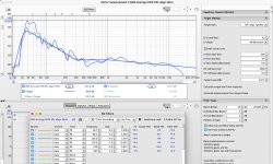
I listening them in my workshop (on the previous photo) with bare walls and notice that they sound good enough, I guess due to well controlled directivity. This build is my first PA system, so I have lack of experience of operating such systems, but AFAIK such system never sound good without EQ-ing for room, fletcher munson curve, crowd density, etc. 215-DCX gives good starting point for that, look at EQ of spatial average in room, low THD at full power of my amps. Also notice that huge 50Hz accent, they are intended to work without subwoofers and they do a lot of chest bump, this underdamping on port frequency present even without +6db PEQ from DSP preset. For me this target curve sounds genre specific, excellent for e.g. techno but questionable with d&b, etc. My amps for woofers are two ICepower 2000AS2, in 20m2 workshop this system (with my EQing) can reach hair shaking, chest vibrating SPL with comfortable and readable mids and highs. This 50Hz bump can be EQ'ed to flat easily, that's what I'm going to do for integrating with subs. Also I would like to have more midbass slap from system, maybe need to play more with target curve and preset.
I guess this bass reflex underdumped alignment is considered bad and boomy for a lot of audiophiles.
Conclusion, they sound good, but I can't witness that I heard they sound excellent yet. I hope I will tune them with subs and more experience to excellent sound.
I guess this bass reflex underdumped alignment is considered bad and boomy for a lot of audiophiles.
Conclusion, they sound good, but I can't witness that I heard they sound excellent yet. I hope I will tune them with subs and more experience to excellent sound.
Attachments
Trying to work out the slant degree of the woofers baffle from the pdf. Can you, please?I had to do some digging. It can be found in the suggested designs: Suggested Designs - B&C Speakers
I've attached their PDF here for reference.
Baffle slant degree pleaseYes, I have build this design, but with some modifications, split to modules and a bit more bracing. Painted with Line-X polyurea.
View attachment 1369344View attachment 1369346View attachment 1369348
I hope this will help. Baffle is troublemaking part, double angled cut 84.83 and 81.4 degree. My recommendations are:
1) Add few extra mm to edges raw part and fit it in place by adjusting cut step by step. I used disc saw. Plywood is not precise, twisting material to hope fit this part in one step, use given angles as estimate.
2) Strongly recommend to redesign it in some CAD by yourself, there were more pitfalls than baffle question
Attachments
- Home
- Loudspeakers
- Multi-Way
- B&C DCX 215